Engineered an OS with physical and virtual memory management, process management, preemptive multitasking, round-robin scheduler, inter-process communication, interrupt, file system, shell, and network interface card driver
JOS
[toc]
PC Bootstrap
Several Questions
- What’s the first command executed when a PC boot up?
- What does BIOS do?
- What does the boot loader do?
- Why do we need to switch from real mode to protected mode?
- What’s the process of the boot up?
- What’s ELF format? What’s .text, .rodat, .data, and .bss? What’s the entry point of a program?
- How to resolve the disparity between the kernel’s link address and its load address?
- How does traceback work?
Physical Address Space
We will now dive into a bit more detail about how a PC starts up. A PC’s physical address space is hard-wired to have the following general layout:
+------------------+  <- 0xFFFFFFFF (4GB)
|      32-bit      |
|  memory mapped   |
|     devices      |
|                  |
/\/\/\/\/\/\/\/\/\/\

/\/\/\/\/\/\/\/\/\/\
|                  |
|      Unused      |
|                  |
+------------------+  <- depends on amount of RAM
|                  |
|                  |
| Extended Memory  |
|                  |
|                  |
+------------------+  <- 0x00100000 (1MB)
|     BIOS ROM     |
+------------------+  <- 0x000F0000 (960KB)
|  16-bit devices, |
|  expansion ROMs  |
+------------------+  <- 0x000C0000 (768KB)
|   VGA Display    |
+------------------+  <- 0x000A0000 (640KB)
|                  |
|    Low Memory    |
|                  |
+------------------+  <- 0x00000000
The first PCs, which were based on the 16-bit Intel 8088 processor, were only capable of addressing 1MB of physical memory. The physical address space of an early PC would therefore start at 0x00000000 but end at 0x000FFFFF instead of 0xFFFFFFFF. The 640KB area marked “Low Memory” was the only random-access memory (RAM) that an early PC could use; in fact the very earliest PCs only could be configured with 16KB, 32KB, or 64KB of RAM!
The 384KB area from 0x000A0000 through 0x000FFFFF was reserved by the hardware for special uses such as video display buffers and firmware held in non-volatile memory. The most important part of this reserved area is the Basic Input/Output System (BIOS), which occupies the 64KB region from 0x000F0000 through 0x000FFFFF. In early PCs the BIOS was held in true read-only memory (ROM), but current PCs store the BIOS in updateable flash memory. The BIOS is responsible for performing basic system initialization such as activating the video card and checking the amount of memory installed. After performing this initialization, the BIOS loads the operating system from some appropriate location such as floppy disk, hard disk, CD-ROM, or the network, and passes control of the machine to the operating system.
When Intel finally “broke the one megabyte barrier” with the 80286 and 80386 processors, which supported 16MB and 4GB physical address spaces respectively, the PC architects nevertheless preserved the original layout for the low 1MB of physical address space in order to ensure backward compatibility with existing software. Modern PCs therefore have a “hole” in physical memory from 0x000A0000 to 0x00100000, dividing RAM into “low” or “conventional memory” (the first 640KB) and “extended memory” (everything else). In addition, some space at the very top of the PC’s 32-bit physical address space, above all physical RAM, is now commonly reserved by the BIOS for use by 32-bit PCI devices.
Recent x86 processors can support more than 4GB of physical RAM, so RAM can extend further above 0xFFFFFFFF. In this case the BIOS must arrange to leave a second hole in the system’s RAM at the top of the 32-bit addressable region, to leave room for these 32-bit devices to be mapped. Because of design limitations JOS will use only the first 256MB of a PC’s physical memory anyway, so for now we will pretend that all PCs have “only” a 32-bit physical address space. But dealing with complicated physical address spaces and other aspects of hardware organization that evolved over many years is one of the important practical challenges of OS development.
BIOS
is GDB’s disassembly of the first instruction to be executed. From this output you can conclude a few things:
- The IBM PC starts executing at physical address 0x000ffff0, which is at the very top of the 64KB area reserved for the ROM BIOS.
- The PC starts executing with
CS = 0xf000andIP = 0xfff0. - The first instruction to be executed is a
jmpinstruction, which jumps to the segmented addressCS = 0xf000andIP = 0xe05b.
Why does QEMU start like this? This is how Intel designed the 8088 processor, which IBM used in their original PC. Because the BIOS in a PC is “hard-wired” to the physical address range 0x000f0000-0x000fffff, this design ensures that the BIOS always gets control of the machine first after power-up or any system restart - which is crucial because on power-up there is no other software anywhere in the machine’s RAM that the processor could execute. The QEMU emulator comes with its own BIOS, which it places at this location in the processor’s simulated physical address space. On processor reset, the (simulated) processor enters real mode and sets CS to 0xf000 and the IP to 0xfff0, so that execution begins at that (CS:IP) segment address. How does the segmented address 0xf000:fff0 turn into a physical address?
To answer that we need to know a bit about real mode addressing. In real mode (the mode that PC starts off in), address translation works according to the formula: physical address = 16 * segment + offset. So, when the PC sets CS to 0xf000 and IP to 0xfff0, the physical address referenced is:
   16 * 0xf000 + 0xfff0   # in hex multiplication by 16 is
   = 0xf0000 + 0xfff0     # easy--just append a 0.
   = 0xffff0
0xffff0 is 16 bytes before the end of the BIOS (0x100000). Therefore we shouldn’t be surprised that the first thing that the BIOS does is jmp backwards to an earlier location in the BIOS; after all how much could it accomplish in just 16 bytes?
Boot Loader
Floppy and hard disks for PCs are divided into 512 byte regions called sectors. A sector is the disk’s minimum transfer granularity: each read or write operation must be one or more sectors in size and aligned on a sector boundary. If the disk is bootable, the first sector is called the boot sector, since this is where the boot loader code resides. When the BIOS finds a bootable floppy or hard disk, it loads the 512-byte boot sector into memory at physical addresses 0x7c00 through 0x7dff, and then uses a jmp instruction to set the CS:IP to 0000:7c00, passing control to the boot loader. Like the BIOS load address, these addresses are fairly arbitrary - but they are fixed and standardized for PCs.
The ability to boot from a CD-ROM came much later during the evolution of the PC, and as a result the PC architects took the opportunity to rethink the boot process slightly. As a result, the way a modern BIOS boots from a CD-ROM is a bit more complicated (and more powerful). CD-ROMs use a sector size of 2048 bytes instead of 512, and the BIOS can load a much larger boot image from the disk into memory (not just one sector) before transferring control to it. For more information, see the “El Torito” Bootable CD-ROM Format Specification.
For 6.828, however, we will use the conventional hard drive boot mechanism, which means that our boot loader must fit into a measly 512 bytes. The boot loader consists of one assembly language source file, boot/boot.S, and one C source file, boot/main.c Look through these source files carefully and make sure you understand what’s going on. The boot loader must perform two main functions:
- First, the boot loader switches the processor from real mode to 32-bit protected mode, because it is only in this mode that software can access all the memory above 1MB in the processor’s physical address space. Protected mode is described briefly in sections 1.2.7 and 1.2.8 of PC Assembly Language, and in great detail in the Intel architecture manuals. At this point you only have to understand that translation of segmented addresses (segment:offset pairs) into physical addresses happens differently in protected mode, and that after the transition offsets are 32 bits instead of 16.
- Second, the boot loader reads the kernel from the hard disk by directly accessing the IDE disk device registers via the x86’s special I/O instructions. If you would like to understand better what the particular I/O instructions here mean, check out the “IDE hard drive controller” section on the 6.828 reference page. You will not need to learn much about programming specific devices in this class: writing device drivers is in practice a very important part of OS development, but from a conceptual or architectural viewpoint it is also one of the least interesting.
#include <inc/mmu.h>

# Start the CPU: switch to 32-bit protected mode, jump into C.
# The BIOS loads this code from the first sector of the hard disk into
# memory at physical address 0x7c00 and starts executing in real mode
# with %cs=0 %ip=7c00.

.set PROT_MODE_CSEG, 0x8         # kernel code segment selector
.set PROT_MODE_DSEG, 0x10        # kernel data segment selector
.set CR0_PE_ON,      0x1         # protected mode enable flag

.globl start
start:
  .code16                     # Assemble for 16-bit mode
  cli                         # Disable interrupts
  cld                         # String operations increment

  # Set up the important data segment registers (DS, ES, SS).
  xorw    %ax,%ax             # Segment number zero
  movw    %ax,%ds             # -> Data Segment
  movw    %ax,%es             # -> Extra Segment
  movw    %ax,%ss             # -> Stack Segment

  # Enable A20:
  #   For backwards compatibility with the earliest PCs, physical
  #   address line 20 is tied low, so that addresses higher than
  #   1MB wrap around to zero by default.  This code undoes this.
seta20.1:
  inb     $0x64,%al               # Wait for not busy
  testb   $0x2,%al
  jnz     seta20.1

  movb    $0xd1,%al               # 0xd1 -> port 0x64
  outb    %al,$0x64

seta20.2:
  inb     $0x64,%al               # Wait for not busy
  testb   $0x2,%al
  jnz     seta20.2

  movb    $0xdf,%al               # 0xdf -> port 0x60
  outb    %al,$0x60

  # Switch from real to protected mode, using a bootstrap GDT
  # and segment translation that makes virtual addresses
  # identical to their physical addresses, so that the
  # effective memory map does not change during the switch.
  lgdt    gdtdesc
  movl    %cr0, %eax
  orl     $CR0_PE_ON, %eax
  movl    %eax, %cr0

  # Jump to next instruction, but in 32-bit code segment.
  # Switches processor into 32-bit mode.
  ljmp    $PROT_MODE_CSEG, $protcseg

  .code32                     # Assemble for 32-bit mode
protcseg:
  # Set up the protected-mode data segment registers
  movw    $PROT_MODE_DSEG, %ax    # Our data segment selector
  movw    %ax, %ds                # -> DS: Data Segment
  movw    %ax, %es                # -> ES: Extra Segment
  movw    %ax, %fs                # -> FS
  movw    %ax, %gs                # -> GS
  movw    %ax, %ss                # -> SS: Stack Segment

  # Set up the stack pointer and call into C.
  movl    $start, %esp
  call bootmain

  # If bootmain returns (it shouldn't), loop.
spin:
  jmp spin

# Bootstrap GDT
.p2align 2                                # force 4 byte alignment
gdt:
  SEG_NULL           # null seg
  SEG(STA_X|STA_R, 0x0, 0xffffffff) # code seg
  SEG(STA_W, 0x0, 0xffffffff)           # data seg

gdtdesc:
  .word   0x17                            # sizeof(gdt) - 1
  .long   gdt                             # address gdt
/* See COPYRIGHT for copyright information. */

#include <inc/mmu.h>
#include <inc/memlayout.h>
#include <inc/trap.h>

# Shift Right Logical
#define SRL(val, shamt)    (((val) >> (shamt)) & ~(-1 << (32 - (shamt))))


###################################################################
# The kernel (this code) is linked at address ~(KERNBASE + 1 Meg),
# but the bootloader loads it at address ~1 Meg.
#
# RELOC(x) maps a symbol x from its link address to its actual
# location in physical memory (its load address).
###################################################################

#define RELOC(x) ((x) - KERNBASE)

#define MULTIBOOT_HEADER_MAGIC (0x1BADB002)
#define MULTIBOOT_HEADER_FLAGS (0)
#define CHECKSUM (-(MULTIBOOT_HEADER_MAGIC + MULTIBOOT_HEADER_FLAGS))

###################################################################
# entry point
###################################################################

.text

# The Multiboot header
.align 4
.long MULTIBOOT_HEADER_MAGIC
.long MULTIBOOT_HEADER_FLAGS
.long CHECKSUM

# '_start' specifies the ELF entry point.  Since we haven't set up
# virtual memory when the bootloader enters this code, we need the
# bootloader to jump to the *physical* address of the entry point.
.globl     _start
_start = RELOC(entry)

.globl entry
entry:
    movw   $0x1234,0x472        # warm boot

    # We haven't set up virtual memory yet, so we're running from
    # the physical address the boot loader loaded the kernel at: 1MB
    # (plus a few bytes).  However, the C code is linked to run at
    # KERNBASE+1MB.  Hence, we set up a trivial page directory that
    # translates virtual addresses [KERNBASE, KERNBASE+4MB) to
    # physical addresses [0, 4MB).  This 4MB region will be
    # sufficient until we set up our real page table in mem_init
    # in lab 2.

    # Load the physical address of entry_pgdir into cr3.  entry_pgdir
    # is defined in entrypgdir.c.
    movl   $(RELOC(entry_pgdir)), %eax
    movl   %eax, %cr3
    # Turn on paging.
    movl   %cr0, %eax
    orl    $(CR0_PE|CR0_PG|CR0_WP), %eax
    movl   %eax, %cr0

    # Now paging is enabled, but we're still running at a low EIP
    # (why is this okay?).  Jump up above KERNBASE before entering
    # C code.
    mov    $relocated, %eax
    jmp    *%eax
relocated:

    # Clear the frame pointer register (EBP)
    # so that once we get into debugging C code,
    # stack backtraces will be terminated properly.
    movl   $0x0,%ebp        # nuke frame pointer

    # Set the stack pointer
    movl   $(bootstacktop),%esp

    # now to C code
    call   i386_init

    # Should never get here, but in case we do, just spin.
spin:   jmp    spin


.data
###################################################################
# boot stack
###################################################################
    .p2align   PGSHIFT       # force page alignment
    .globl    bootstack
bootstack:
    .space    KSTKSIZE
    .globl    bootstacktop
bootstacktop:
/**********************************************************************
 * This a dirt simple boot loader, whose sole job is to boot
 * an ELF kernel image from the first IDE hard disk.
 *
 * DISK LAYOUT
 *  * This program(boot.S and main.c) is the bootloader.  It should
 *    be stored in the first sector of the disk.
 *
 *  * The 2nd sector onward holds the kernel image.
 *
 *  * The kernel image must be in ELF format.
 *
 * BOOT UP STEPS
 *  * when the CPU boots it loads the BIOS into memory and executes it
 *
 *  * the BIOS intializes devices, sets of the interrupt routines, and
 *    reads the first sector of the boot device(e.g., hard-drive)
 *    into memory and jumps to it.
 *
 *  * Assuming this boot loader is stored in the first sector of the
 *    hard-drive, this code takes over...
 *
 *  * control starts in boot.S -- which sets up protected mode,
 *    and a stack so C code then run, then calls bootmain()
 *
 *  * bootmain() in this file takes over, reads in the kernel and jumps to it.
 **********************************************************************/

#define SECTSIZE    512
#define ELFHDR     ((struct Elf *) 0x10000) // scratch space

void readsect(void*, uint32_t);
void readseg(uint32_t, uint32_t, uint32_t);

void
bootmain(void)
{
    struct Proghdr *ph, *eph;
    int i;

    // read 1st page off disk
    readseg((uint32_t) ELFHDR, SECTSIZE*8, 0);

    // is this a valid ELF?
    if (ELFHDR->e_magic != ELF_MAGIC)
       goto bad;

    // load each program segment (ignores ph flags)
    ph = (struct Proghdr *) ((uint8_t *) ELFHDR + ELFHDR->e_phoff);
    eph = ph + ELFHDR->e_phnum;
    for (; ph < eph; ph++) {
       // p_pa is the load address of this segment (as well
       // as the physical address)
       readseg(ph->p_pa, ph->p_memsz, ph->p_offset);
       for (i = 0; i < ph->p_memsz - ph->p_filesz; i++) {
          *((char *) ph->p_pa + ph->p_filesz + i) = 0;
       }
    }

    // call the entry point from the ELF header
    // note: does not return!
    ((void (*)(void)) (ELFHDR->e_entry))();

bad:
    outw(0x8A00, 0x8A00);
    outw(0x8A00, 0x8E00);
    while (1)
       /* do nothing */;
}
ELF
To make sense out of boot/main.c you’ll need to know what an ELF binary is. When you compile and link a C program such as the JOS kernel, the compiler transforms each C source (‘.c’) file into an object (‘.o’) file containing assembly language instructions encoded in the binary format expected by the hardware. The linker then combines all of the compiled object files into a single binary image such as obj/kern/kernel, which in this case is a binary in the ELF format, which stands for “Executable and Linkable Format”.
Full information about this format is available in the ELF specification on our reference page, but you will not need to delve very deeply into the details of this format in this class. Although as a whole the format is quite powerful and complex, most of the complex parts are for supporting dynamic loading of shared libraries, which we will not do in this class. The Wikipedia page has a short description.
For purposes of 6.828, you can consider an ELF executable to be a header with loading information, followed by several program sections, each of which is a contiguous chunk of code or data intended to be loaded into memory at a specified address. The boot loader does not modify the code or data; it loads it into memory and starts executing it.
An ELF binary starts with a fixed-length ELF header, followed by a variable-length program header listing each of the program sections to be loaded. The C definitions for these ELF headers are in inc/elf.h. The program sections we’re interested in are:
.text: The program’s executable instructions..rodata: Read-only data, such as ASCII string constants produced by the C compiler. (We will not bother setting up the hardware to prohibit writing, however.).data: The data section holds the program’s initialized data, such as global variables declared with initializers likeint x = 5;.
When the linker computes the memory layout of a program, it reserves space for uninitialized global variables, such as int x;, in a section called .bss that immediately follows .data in memory. C requires that “uninitialized” global variables start with a value of zero. Thus there is no need to store contents for .bss in the ELF binary; instead, the linker records just the address and size of the .bss section. The loader or the program itself must arrange to zero the .bss section.
The link address of a section is the memory address from which the section expects to execute. The linker encodes the link address in the binary in various ways, such as when the code needs the address of a global variable, with the result that a binary usually won’t work if it is executing from an address that it is not linked for. (It is possible to generate position-independent code that does not contain any such absolute addresses. This is used extensively by modern shared libraries, but it has performance and complexity costs, so we won’t be using it in 6.828.)
The program headers are then listed under “Program Headers” in the output of objdump. The areas of the ELF object that need to be loaded into memory are those that are marked as “LOAD”. Other information for each program header is given, such as the virtual address (“vaddr”), the physical address (“paddr”), and the size of the loaded area (“memsz” and “filesz”).
Back in boot/main.c, the ph->p_pa field of each program header contains the segment’s destination physical address (in this case, it really is a physical address, though the ELF specification is vague on the actual meaning of this field).
The BIOS loads the boot sector into memory starting at address 0x7c00, so this is the boot sector’s load address. This is also where the boot sector executes from, so this is also its link address. We set the link address by passing -Ttext 0x7C00 to the linker in boot/Makefrag, so the linker will produce the correct memory addresses in the generated code.
Position Dependence
When you inspected the boot loader’s link and load addresses above, they matched perfectly, but there was a (rather large) disparity between the kernel’s link address (as printed by objdump) and its load address. Go back and check both and make sure you can see what we’re talking about. (Linking the kernel is more complicated than the boot loader, so the link and load addresses are at the top of kern/kernel.ld.)
Operating system kernels often like to be linked and run at very high virtual address, such as 0xf0100000, in order to leave the lower part of the processor’s virtual address space for user programs to use. The reason for this arrangement will become clearer in the next lab.
Many machines don’t have any physical memory at address 0xf0100000, so we can’t count on being able to store the kernel there. Instead, we will use the processor’s memory management hardware to map virtual address 0xf0100000 (the link address at which the kernel code expects to run) to physical address 0x00100000 (where the boot loader loaded the kernel into physical memory). This way, although the kernel’s virtual address is high enough to leave plenty of address space for user processes, it will be loaded in physical memory at the 1MB point in the PC’s RAM, just above the BIOS ROM. This approach requires that the PC have at least a few megabytes of physical memory (so that physical address 0x00100000 works), but this is likely to be true of any PC built after about 1990.
In fact, in the next lab, we will map the entire bottom 256MB of the PC’s physical address space, from physical addresses 0x00000000 through 0x0fffffff, to virtual addresses 0xf0000000 through 0xffffffff respectively. You should now see why JOS can only use the first 256MB of physical memory.
For now, we’ll just map the first 4MB of physical memory, which will be enough to get us up and running. We do this using the hand-written, statically-initialized page directory and page table in kern/entrypgdir.c. For now, you don’t have to understand the details of how this works, just the effect that it accomplishes. Up until kern/entry.S sets the CR0_PG flag, memory references are treated as physical addresses (strictly speaking, they’re linear addresses, but boot/boot.S set up an identity mapping from linear addresses to physical addresses and we’re never going to change that). Once CR0_PG is set, memory references are virtual addresses that get translated by the virtual memory hardware to physical addresses. entry_pgdir translates virtual addresses in the range 0xf0000000 through 0xf0400000 to physical addresses 0x00000000 through 0x00400000, as well as virtual addresses 0x00000000 through 0x00400000 to physical addresses 0x00000000 through 0x00400000. Any virtual address that is not in one of these two ranges will cause a hardware exception which, since we haven’t set up interrupt handling yet, will cause QEMU to dump the machine state and exit (or endlessly reboot if you aren’t using the 6.828-patched version of QEMU).
Stack and Traceback
The x86 stack pointer (esp register) points to the lowest location on the stack that is currently in use. Everything below that location in the region reserved for the stack is free. Pushing a value onto the stack involves decreasing the stack pointer and then writing the value to the place the stack pointer points to. Popping a value from the stack involves reading the value the stack pointer points to and then increasing the stack pointer. In 32-bit mode, the stack can only hold 32-bit values, and esp is always divisible by four. Various x86 instructions, such as call, are “hard-wired” to use the stack pointer register.
The ebp (base pointer) register, in contrast, is associated with the stack primarily by software convention. On entry to a C function, the function’s prologue code normally saves the previous function’s base pointer by pushing it onto the stack, and then copies the current esp value into ebp for the duration of the function. If all the functions in a program obey this convention, then at any given point during the program’s execution, it is possible to trace back through the stack by following the chain of saved ebp pointers and determining exactly what nested sequence of function calls caused this particular point in the program to be reached. This capability can be particularly useful, for example, when a particular function causes an assert failure or panic because bad arguments were passed to it, but you aren’t sure who passed the bad arguments. A stack backtrace lets you find the offending function.
The stack structure is like this:
              4               0
              +---------------+ HIGH
              | saved %ebp    | <---+
              | saved %esi    |     |
stack frame 0 | arg 4 (%ebx)  |     |
              | arg 3         |     |
              | arg 2         |     |
              | arg 1 (%esi)? |     |
              | arg 0 (%eax)  |     |
              | saved %eip    |     |
              +---------------+     |
    %ebp ---> | saved %ebp    | <---+
              | saved %esi    |     |
stack frame x | arg 4 (%ebx)  |     |
              | arg 3         |     |
              | arg 2         |     |
              | arg 1 (%esi)? |     |
              | arg 0 (%eax)  |     |
              | saved %eip    |     |
              +---------------+     |
    %ebp ---> | saved %ebp    | ----+
              | something     |
    %esp ---> +---------------+ LOW
In kern/kern.ld, we can find that __STAB_* points to the .stab section of the elf file which contains the debugging information, as known as the symbol table. It was linked to the kernel and loaded to the kernel memory. The output of objdump -h obj/kern/kernel command shows that the kernel does contain a .stab and a .stabstr section
and objdump -G obj/kern/kernel command will print the symbol table out. So debuginfo_eip() can read debugging information like function names from the .stab section and that’s why __STAB_* is used.
In kern/kdebug.c, we notice that debuginfo_eip() uses a struct Eipdebuginfo structure to pass the information we want, and the struct was defined in kern/kdebug.c like that.
// Debug information about a particular instruction pointer
struct Eipdebuginfo {
	const char *eip_file;		// Source code filename for EIP
	int eip_line;			// Source code linenumber for EIP

	const char *eip_fn_name;	// Name of function containing EIP
					//  - Note: not null terminated!
	int eip_fn_namelen;		// Length of function name
	uintptr_t eip_fn_addr;		// Address of start of function
	int eip_fn_narg;		// Number of function arguments
};
Noticed that eip_fn_name is not a null-terminated string, the lab page hinted that we can use printf("%.*s", length, string) to print non-null-terminated strings.
Memory Management
Physical Memory Management
Physical memory is managed by pages. Physical pages are managed by the kernel using the struct PageInfo structure.
The kernel keeps an array of struct PageInfo to keep track of all the physical pages.
The kernel also keeps a linked list of free pages that can be allocated.
// These variables are set in mem_init()
pde_t *kern_pgdir;		// Kernel's initial page directory
struct PageInfo *pages;		// Physical page state array
static struct PageInfo *page_free_list;	// Free list of physical pages
/*
 * Page descriptor structures, mapped at UPAGES.
 * Read/write to the kernel, read-only to user programs.
 *
 * Each struct PageInfo stores metadata for one physical page.
 * Is it NOT the physical page itself, but there is a one-to-one
 * correspondence between physical pages and struct PageInfo's.
 * You can map a struct PageInfo * to the corresponding physical address
 * with page2pa() in kern/pmap.h.
 */
struct PageInfo {
	// Next page on the free list.
	struct PageInfo *pp_link;

	// pp_ref is the count of pointers (usually in page table entries)
	// to this page, for pages allocated using page_alloc.
	// Pages allocated at boot time using pmap.c's
	// boot_alloc do not have valid reference count fields.

	uint16_t pp_ref;
};
Allocation before initializing the page free list
Before allocating the physical pages using the free list,
we need to allocate the memory for the PageInfo in the free list.
To do the self-lifting, we use a simple allocator called boot_alloc
that allocates memory by numerically incrementing a global variable nextfree.
static void *
boot_alloc(uint32_t n)
{
	static char *nextfree;	// virtual address of next byte of free memory
	char *result;

	// Initialize nextfree if this is the first time.
	// 'end' is a magic symbol automatically generated by the linker,
	// which points to the end of the kernel's bss segment:
	// the first virtual address that the linker did *not* assign
	// to any kernel code or global variables.
	if (!nextfree) {
		extern char end[];
		nextfree = ROUNDUP((char *) end, PGSIZE);
	}

	// Allocate a chunk large enough to hold 'n' bytes, then update
	// nextfree.  Make sure nextfree is kept aligned
	// to a multiple of PGSIZE.
	//
	// LAB 2: Your code here.
    if(n == 0) {
        return nextfree;
    }else if(n > 0) {
        result = nextfree;
        nextfree += ROUNDUP(n, PGSIZE);
        return result;
    }

	return NULL;
}
Initialization
Initialize page structure and memory free list.
	//////////////////////////////////////////////////////////////////////
    // Allocate an array of npages 'struct PageInfo's and store it in 'pages'.
    // The kernel uses this array to keep track of physical pages: for
    // each physical page, there is a corresponding struct PageInfo in this
    // array.  'npages' is the number of physical pages in memory.  Use memset
    // to initialize all fields of each struct PageInfo to 0.
    // Your code goes here:
    pages = (struct PageInfo *) boot_alloc(npages * sizeof(struct PageInfo));
    memset(pages, 0, npages * sizeof(struct PageInfo));
	//////////////////////////////////////////////////////////////////////
	// Now that we've allocated the initial kernel data structures, we set
	// up the list of free physical pages. Once we've done so, all further
	// memory management will go through the page_* functions. In
	// particular, we can now map memory using boot_map_region
	// or page_insert
	page_init();
void
page_init(void)
{
	// The example code here marks all physical pages as free.
	// However this is not truly the case.  What memory is free?
	//  1) Mark physical page 0 as in use.
	//     This way we preserve the real-mode IDT and BIOS structures
	//     in case we ever need them.  (Currently we don't, but...)
	//  2) The rest of base memory, [PGSIZE, npages_basemem * PGSIZE)
	//     is free.
	//  3) Then comes the IO hole [IOPHYSMEM, EXTPHYSMEM), which must
	//     never be allocated.
	//  4) Then extended memory [EXTPHYSMEM, ...).
	//     Some of it is in use, some is free. Where is the kernel
	//     in physical memory?  Which pages are already in use for
	//     page tables and other data structures?
	//
	// Change the code to reflect this.
	// NB: DO NOT actually touch the physical memory corresponding to
	// free pages!
    pages[0].pp_ref = 1;
    pages[0].pp_link = NULL;

    for(int i = 1; i < npages_basemem; i++) {
        pages[i].pp_ref = 0;
        pages[i].pp_link = page_free_list;
        page_free_list = &pages[i];
    }

    for(int i = IOPHYSMEM / PGSIZE; i < EXTPHYSMEM / PGSIZE; i++) {
        pages[i].pp_ref = 1;
        pages[i].pp_link = NULL;
    }

    int boot_alloc_end = PADDR(boot_alloc(0)) / PGSIZE;
    for(int i = EXTPHYSMEM / PGSIZE; i < boot_alloc_end; i++) {
        pages[i].pp_ref = 1;
        pages[i].pp_link = NULL;
    }

    for(int i = boot_alloc_end; i < npages; i++) {
        pages[i].pp_ref = 0;
        pages[i].pp_link = page_free_list;
        page_free_list = &pages[i];
    }
}
Allocation after initializing the page free list
To allocate a page, we need to remove a page from the free list.
struct PageInfo *
page_alloc(int alloc_flags)
{
	// Fill this function in
    struct PageInfo* free_page = page_free_list;
    if(free_page == NULL) {
        return NULL;
    }
    page_free_list = free_page->pp_link;
    free_page->pp_link = NULL;

    if(alloc_flags & ALLOC_ZERO) {
        memset(page2kva(free_page), 0, PGSIZE);
    }
	return free_page;
}
Freeing
When a physical page is no longer in use, we need to decrement the reference count of the page so that the page can be freed when the reference count reaches 0.
void
page_decref(struct PageInfo* pp)
{
	if (--pp->pp_ref == 0)
		page_free(pp);
}
To free a page, we need to return the page to the free list.
//
// Return a page to the free list.
// (This function should only be called when pp->pp_ref reaches 0.)
//
void
page_free(struct PageInfo *pp)
{
	// Fill this function in
	// Hint: You may want to panic if pp->pp_ref is nonzero or
	// pp->pp_link is not NULL.
    if(pp->pp_ref != 0 || pp->pp_link != NULL) {
        panic("page_free: pp->pp_ref != 0 || pp->pp_link != NULL");
    }

    pp->pp_link = page_free_list;
    page_free_list = pp;
}
Virtual Memory Management
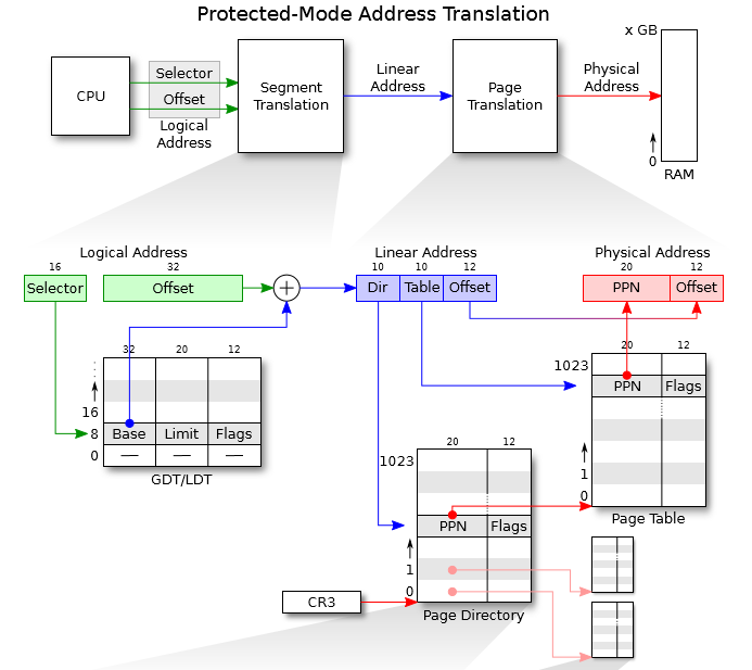
In x86 terminology, a virtual address consists of a segment selector and an offset within the segment. A linear address is what you get after segment translation but before page translation. A physical address is what you finally get after both segment and page translation and what ultimately goes out on the hardware bus to your RAM.
           Selector  +--------------+         +-----------+
          ---------->|              |         |           |
                     | Segmentation |         |  Paging   |
Software             |              |-------->|           |---------->  RAM
            Offset   |  Mechanism   |         | Mechanism |
          ---------->|              |         |           |
                     +--------------+         +-----------+
            Virtual                   Linear                Physical
Layout
Every process has its own virtual address space. The whole virtual address space is divided into kernel space and user space. Both of them can be divided into many virtual pages. To read or write data in a virtual page, process usually needs to give a linear address that consists of a segment base and an offset. Adding the segment base to the offset gives the logical address of the data. Then the logical address is translated to a physical address using the 2-level page table.
The following is a general virtual memory layout of a process in JOS.
/*
 * Virtual memory map:                                Permissions
 *                                                    kernel/user
 *
 *    4 Gig -------->  +------------------------------+
 *                     |                              | RW/--
 *                     ~~~~~~~~~~~~~~~~~~~~~~~~~~~~~~~~
 *                     :              .               :
 *                     :              .               :
 *                     :              .               :
 *                     |~~~~~~~~~~~~~~~~~~~~~~~~~~~~~~| RW/--
 *                     |                              | RW/--
 *                     |   Remapped Physical Memory   | RW/--
 *                     |                              | RW/--
 *    KERNBASE, ---->  +------------------------------+ 0xf0000000      --+
 *    KSTACKTOP        |     CPU0's Kernel Stack      | RW/--  KSTKSIZE   |
 *                     | - - - - - - - - - - - - - - -|                   |
 *                     |      Invalid Memory (*)      | --/--  KSTKGAP    |
 *                     +------------------------------+                   |
 *                     |     CPU1's Kernel Stack      | RW/--  KSTKSIZE   |
 *                     | - - - - - - - - - - - - - - -|                 PTSIZE
 *                     |      Invalid Memory (*)      | --/--  KSTKGAP    |
 *                     +------------------------------+                   |
 *                     :              .               :                   |
 *                     :              .               :                   |
 *    MMIOLIM ------>  +------------------------------+ 0xefc00000      --+
 *                     |       Memory-mapped I/O      | RW/--  PTSIZE
 * ULIM, MMIOBASE -->  +------------------------------+ 0xef800000
 *                     |  Cur. Page Table (User R-)   | R-/R-  PTSIZE
 *    UVPT      ---->  +------------------------------+ 0xef400000
 *                     |          RO PAGES            | R-/R-  PTSIZE
 *    UPAGES    ---->  +------------------------------+ 0xef000000
 *                     |           RO ENVS            | R-/R-  PTSIZE
 * UTOP,UENVS ------>  +------------------------------+ 0xeec00000
 * UXSTACKTOP -/       |     User Exception Stack     | RW/RW  PGSIZE
 *                     +------------------------------+ 0xeebff000
 *                     |       Empty Memory (*)       | --/--  PGSIZE
 *    USTACKTOP  --->  +------------------------------+ 0xeebfe000
 *                     |      Normal User Stack       | RW/RW  PGSIZE
 *                     +------------------------------+ 0xeebfd000
 *                     |                              |
 *                     |                              |
 *                     ~~~~~~~~~~~~~~~~~~~~~~~~~~~~~~~~
 *                     .                              .
 *                     .                              .
 *                     .                              .
 *                     |~~~~~~~~~~~~~~~~~~~~~~~~~~~~~~|
 *                     |     Program Data & Heap      |
 *    UTEXT -------->  +------------------------------+ 0x00800000
 *    PFTEMP ------->  |       Empty Memory (*)       |        PTSIZE
 *                     |                              |
 *    UTEMP -------->  +------------------------------+ 0x00400000      --+
 *                     |       Empty Memory (*)       |                   |
 *                     | - - - - - - - - - - - - - - -|                   |
 *                     |  User STAB Data (optional)   |                 PTSIZE
 *    USTABDATA ---->  +------------------------------+ 0x00200000        |
 *                     |       Empty Memory (*)       |                   |
 *    0 ------------>  +------------------------------+                 --+
 *
 * (*) Note: The kernel ensures that "Invalid Memory" is *never* mapped.
 *     "Empty Memory" is normally unmapped, but user programs may map pages
 *     there if desired.  JOS user programs map pages temporarily at UTEMP.
 */


// All physical memory mapped at this address
#define	KERNBASE	0xF0000000

// At IOPHYSMEM (640K) there is a 384K hole for I/O.  From the kernel,
// IOPHYSMEM can be addressed at KERNBASE + IOPHYSMEM.  The hole ends
// at physical address EXTPHYSMEM.
#define IOPHYSMEM	0x0A0000
#define EXTPHYSMEM	0x100000

// Kernel stack.
#define KSTACKTOP	KERNBASE
#define KSTKSIZE	(8*PGSIZE)   		// size of a kernel stack
#define KSTKGAP		(8*PGSIZE)   		// size of a kernel stack guard

// Memory-mapped IO.
#define MMIOLIM		(KSTACKTOP - PTSIZE)
#define MMIOBASE	(MMIOLIM - PTSIZE)

#define ULIM		(MMIOBASE)

/*
 * User read-only mappings! Anything below here til UTOP are readonly to user.
 * They are global pages mapped in at env allocation time.
 */

// User read-only virtual page table (see 'uvpt' below)
#define UVPT		(ULIM - PTSIZE)
// Read-only copies of the Page structures
#define UPAGES		(UVPT - PTSIZE)
// Read-only copies of the global env structures
#define UENVS		(UPAGES - PTSIZE)

/*
 * Top of user VM. User can manipulate VA from UTOP-1 and down!
 */

// Top of user-accessible VM
#define UTOP		UENVS
// Top of one-page user exception stack
#define UXSTACKTOP	UTOP
// Next page left invalid to guard against exception stack overflow; then:
// Top of normal user stack
#define USTACKTOP	(UTOP - 2*PGSIZE)

// Where user programs generally begin
#define UTEXT		(2*PTSIZE)

// Used for temporary page mappings.  Typed 'void*' for convenience
#define UTEMP		((void*) PTSIZE)
// Used for temporary page mappings for the user page-fault handler
// (should not conflict with other temporary page mappings)
#define PFTEMP		(UTEMP + PTSIZE - PGSIZE)
// The location of the user-level STABS data structure
#define USTABDATA	(PTSIZE / 2)

// Physical address of startup code for non-boot CPUs (APs)
#define MPENTRY_PADDR	0x7000
Initialization
JOS uses a two-level page table to manage the virtual memory. The initialization of kernel space involves allocating a physical page for the page directory and allocating some pages for the kernel.
// Set up a two-level page table:
//    kern_pgdir is its linear (virtual) address of the root
//
// This function only sets up the kernel part of the address space
// (ie. addresses >= UTOP).  The user part of the address space
// will be set up later.
//
// From UTOP to ULIM, the user is allowed to read but not write.
// Above ULIM the user cannot read or write.
void
mem_init(void)
	// create initial page directory.
	kern_pgdir = (pde_t *) boot_alloc(PGSIZE);
	memset(kern_pgdir, 0, PGSIZE);
	//////////////////////////////////////////////////////////////////////
	// Map 'pages' read-only by the user at linear address UPAGES
	// Permissions:
	//    - the new image at UPAGES -- kernel R, user R
	//      (ie. perm = PTE_U | PTE_P)
	//    - pages itself -- kernel RW, user NONE
	// Your code goes here:
    boot_map_region(kern_pgdir, UPAGES, ROUNDUP(npages * sizeof(struct PageInfo), PGSIZE), PADDR(pages), PTE_U | PTE_P);

	//////////////////////////////////////////////////////////////////////
	// Map the 'envs' array read-only by the user at linear address UENVS
	// (ie. perm = PTE_U | PTE_P).
	// Permissions:
	//    - the new image at UENVS  -- kernel R, user R
	//    - envs itself -- kernel RW, user NONE
	// LAB 3: Your code here.
    boot_map_region(kern_pgdir, UENVS, ROUNDUP(NENV * sizeof(struct Env), PGSIZE), PADDR(envs), PTE_U | PTE_P);

	//////////////////////////////////////////////////////////////////////
	// Use the physical memory that 'bootstack' refers to as the kernel
	// stack.  The kernel stack grows down from virtual address KSTACKTOP.
	// We consider the entire range from [KSTACKTOP-PTSIZE, KSTACKTOP)
	// to be the kernel stack, but break this into two pieces:
	//     * [KSTACKTOP-KSTKSIZE, KSTACKTOP) -- backed by physical memory
	//     * [KSTACKTOP-PTSIZE, KSTACKTOP-KSTKSIZE) -- not backed; so if
	//       the kernel overflows its stack, it will fault rather than
	//       overwrite memory.  Known as a "guard page".
	//     Permissions: kernel RW, user NONE
	// Your code goes here:
    boot_map_region(kern_pgdir, KSTACKTOP - KSTKSIZE, KSTKSIZE, PADDR(bootstack), PTE_W | PTE_P);
//    boot_map_region(kern_pgdir, KSTACKTOP - PTSIZE, PTSIZE - KSTKSIZE, 0, PTE_W | PTE_P);

	//////////////////////////////////////////////////////////////////////
	// Map all of physical memory at KERNBASE.
	// Ie.  the VA range [KERNBASE, 2^32) should map to
	//      the PA range [0, 2^32 - KERNBASE)
	// We might not have 2^32 - KERNBASE bytes of physical memory, but
	// we just set up the mapping anyway.
	// Permissions: kernel RW, user NONE
	// Your code goes here:
    boot_map_region(kern_pgdir, KERNBASE, 0xffffffff - KERNBASE, 0, PTE_W | PTE_P);
//
// Map [va, va+size) of virtual address space to physical [pa, pa+size)
// in the page table rooted at pgdir.  Size is a multiple of PGSIZE, and
// va and pa are both page-aligned.
// Use permission bits perm|PTE_P for the entries.
//
// This function is only intended to set up the ``static'' mappings
// above UTOP. As such, it should *not* change the pp_ref field on the
// mapped pages.
//
// Hint: the TA solution uses pgdir_walk
static void
boot_map_region(pde_t *pgdir, uintptr_t va, size_t size, physaddr_t pa, int perm)
{
	// Fill this function in
    for(int i = 0; i < size; i += PGSIZE) {
        pte_t* pte = pgdir_walk(pgdir, (void *) va, 1);
        *pte = pa | perm | PTE_P;
        va += PGSIZE;
        pa += PGSIZE;
    }
}
To get the page table entry for a virtual address, we need to walk the page directory and the page table.
// Given 'pgdir', a pointer to a page directory, pgdir_walk returns
// a pointer to the page table entry (PTE) for linear address 'va'.
// This requires walking the two-level page table structure.
//
// The relevant page table page might not exist yet.
// If this is true, and create == false, then pgdir_walk returns NULL.
// Otherwise, pgdir_walk allocates a new page table page with page_alloc.
//    - If the allocation fails, pgdir_walk returns NULL.
//    - Otherwise, the new page's reference count is incremented,
//	the page is cleared,
//	and pgdir_walk returns a pointer into the new page table page.
//
// Hint 1: you can turn a PageInfo * into the physical address of the
// page it refers to with page2pa() from kern/pmap.h.
//
// Hint 2: the x86 MMU checks permission bits in both the page directory
// and the page table, so it's safe to leave permissions in the page
// directory more permissive than strictly necessary.
//
// Hint 3: look at inc/mmu.h for useful macros that manipulate page
// table and page directory entries.
//
pte_t *
pgdir_walk(pde_t *pgdir, const void *va, int create)
{
	// Fill this function in
    pde_t* pde = &pgdir[PDX(va)];
    if(!(*pde & PTE_P)) {
        if(!create) {
            return NULL;
        }
        struct PageInfo* new_page = page_alloc(ALLOC_ZERO);
        if(new_page == NULL) {
            return NULL;
        }
        new_page->pp_ref++;
        *pde = page2pa(new_page) | PTE_P | PTE_W | PTE_U;
    }
    pte_t* pte = (pte_t *) KADDR(PTE_ADDR(*pde));
    return &pte[PTX(va)];
}
Map a physical page to a virtual address
To map a physical page to a virtual address, we need to find the page table entry for the virtual address and set the entry to the physical address.
int
page_insert(pde_t *pgdir, struct PageInfo *pp, void *va, int perm)
{
	// Fill this function in
    pte_t* pte = pgdir_walk(pgdir, va, 1);
    if(pte == NULL) {
        return -E_NO_MEM;
    }
    pp->pp_ref++;
    if(*pte & PTE_P) {
        page_remove(pgdir, va);
    }
    *pte = page2pa(pp) | perm | PTE_P;
    return 0;
}
Unmap a physical page from a virtual address
To unmap a physical page from a virtual address, we need to find the page table entry for the virtual address and set the entry to 0. Also, we need to decrement the reference count of the physical page.
void
page_remove(pde_t *pgdir, void *va)
{
	// Fill this function in
    pte_t* pte;
    struct PageInfo* page = page_lookup(pgdir, va, &pte);
    if(page == NULL) {
        return;
    }
    page_decref(page);
    *pte = 0;
    tlb_invalidate(pgdir, va);
    return;
}
Process Management
In JOS, a process is called an environment. Each environment has its own virtual address space. The kernel provides a mechanism for creating, destroying, and managing environments.
struct Env {
	struct Trapframe env_tf;	// Saved registers when switching context
	struct Env *env_link;		// Next free Env
	envid_t env_id;			// Unique environment identifier
	envid_t env_parent_id;		// env_id of this env's parent
	enum EnvType env_type;		// Indicates special system environments
	unsigned env_status;		// Status of the environment
	uint32_t env_runs;		// Number of times environment has run

	// Address space
	pde_t *env_pgdir;		// Kernel virtual address of page dir
};
Here’s what the Env fields are for:
-
env_tf:
This structure, defined in
inc/trap.h, holds the saved register values for the environment while that environment is not running: i.e., when the kernel or a different environment is running. The kernel saves these when switching from user to kernel mode, so that the environment can later be resumed where it left off. -
env_link:
This is a link to the next
Envon theenv_free_list.env_free_listpoints to the first free environment on the list. -
env_id:
The kernel stores here a value that uniquely identifiers the environment currently using this
Envstructure (i.e., using this particular slot in theenvsarray). After a user environment terminates, the kernel may re-allocate the sameEnvstructure to a different environment - but the new environment will have a differentenv_idfrom the old one even though the new environment is re-using the same slot in theenvsarray. -
env_parent_id:
The kernel stores here the
env_idof the environment that created this environment. In this way the environments can form a “family tree,” which will be useful for making security decisions about which environments are allowed to do what to whom. -
env_type:
This is used to distinguish special environments. For most environments, it will be
ENV_TYPE_USER. We’ll introduce a few more types for special system service environments in later labs. -
env_status:
This variable holds one of the following values:
ENV_FREE:Indicates that theEnvstructure is inactive, and therefore on theenv_free_list.ENV_RUNNABLE:Indicates that theEnvstructure represents an environment that is waiting to run on the processor.ENV_RUNNING:Indicates that theEnvstructure represents the currently running environment.ENV_NOT_RUNNABLE:Indicates that theEnvstructure represents a currently active environment, but it is not currently ready to run: for example, because it is waiting for an interprocess communication (IPC) from another environment.ENV_DYING:Indicates that theEnvstructure represents a zombie environment. A zombie environment will be freed the next time it traps to the kernel. We will not use this flag until Lab 4. -
env_pgdir:
This variable holds the kernel virtual address of this environment’s page directory.
Like a Unix process, a JOS environment couples the concepts of “thread” and “address space”. The thread is defined primarily by the saved registers (the env_tf field), and the address space is defined by the page directory and page tables pointed to by env_pgdir. To run an environment, the kernel must set up the CPU with both the saved registers and the appropriate address space.
Initialization
The processes are organized in a array so that we can easily find a process by its id.
They are also linked in a list that contains all the free processes that can be allocated.
The array and the linked list are initialized in the function env_init in the file kern/env.c.
void
env_init(void)
{
	// Set up envs array
	// LAB 3: Your code here.
    for(int i = 0; i < NENV - 1; i++) {
        envs[i].env_id = 0;
        envs[i].env_status = ENV_FREE;
        envs[i].env_link = &envs[i+1];
    }
    envs[NENV - 1].env_id = 0;
    envs[NENV - 1].env_status = ENV_FREE;
    envs[NENV - 1].env_link = NULL;
    env_free_list = &envs[0];

	// Per-CPU part of the initialization
	env_init_percpu();
}
A single process can be accessed using its env_id.
e = &envs[ENVX(envid)];
Allocation
To create a new process, we need to initialize the fields of the struct Env.
int
env_alloc(struct Env **newenv_store, envid_t parent_id)
- Allocate a new process from the free list.
if (!(e = env_free_list)) { panic("env_alloc: no free envs"); return -E_NO_FREE_ENV; } - Allocate and set up a page directory for the new environment.
 if ((r = env_setup_vm(e)) < 0)
     return r;
In JOS, the kernel memory is mapped in the page directory of each process so that the kernel can be accessed from the user space.
memcpy(e->env_pgdir, kern_pgdir, PGSIZE); - Generate an environment ID for the new environment.
// Generate an env_id for this environment. generation = (e->env_id + (1 << ENVGENSHIFT)) & ~(NENV - 1); if (generation <= 0) // Don't create a negative env_id. generation = 1 << ENVGENSHIFT; e->env_id = generation | (e - envs); - Set the appropriate status for the new environment.
// Set the basic status variables. e->env_parent_id = parent_id; e->env_type = ENV_TYPE_USER; e->env_status = ENV_RUNNABLE; e->env_runs = 0; - Set the trapframe for the new environment.
 // Clear out all the saved register state,
 // to prevent the register values
 // of a prior environment inhabiting this Env structure
 // from "leaking" into our new environment.
 memset(&e->env_tf, 0, sizeof(e->env_tf));

 // Set up appropriate initial values for the segment registers.
 // GD_UD is the user data segment selector in the GDT, and
 // GD_UT is the user text segment selector (see inc/memlayout.h).
 // The low 2 bits of each segment register contains the
 // Requestor Privilege Level (RPL); 3 means user mode.  When
 // we switch privilege levels, the hardware does various
 // checks involving the RPL and the Descriptor Privilege Level
 // (DPL) stored in the descriptors themselves.
 e->env_tf.tf_ds = GD_UD | 3;
 e->env_tf.tf_es = GD_UD | 3;
 e->env_tf.tf_ss = GD_UD | 3;
 e->env_tf.tf_esp = USTACKTOP;
 e->env_tf.tf_cs = GD_UT | 3;
 // You will set e->env_tf.tf_eip later.

 // Enable interrupts while in user mode.
 // LAB 4: Your code here.
 e->env_tf.tf_eflags |= FL_IF;
Freeing
To free a process, we need to free the memory that was allocated for the process and return the process to the free list.
- Free the pages, page tables, and the page directory of the process.
// Flush all mapped pages in the user portion of the address space static_assert(UTOP % PTSIZE == 0); for (pdeno = 0; pdeno < PDX(UTOP); pdeno++) { // only look at mapped page tables if (!(e->env_pgdir[pdeno] & PTE_P)) continue; // find the pa and va of the page table pa = PTE_ADDR(e->env_pgdir[pdeno]); pt = (pte_t*) KADDR(pa); // unmap all PTEs in this page table for (pteno = 0; pteno <= PTX(~0); pteno++) { if (pt[pteno] & PTE_P) page_remove(e->env_pgdir, PGADDR(pdeno, pteno, 0)); } // free the page table itself e->env_pgdir[pdeno] = 0; page_decref(pa2page(pa)); } // free the page directory pa = PADDR(e->env_pgdir); e->env_pgdir = 0; page_decref(pa2page(pa)); - Return the process to the free list.
 // return the environment to the free list
 e->env_status = ENV_FREE;
 e->env_link = env_free_list;
 env_free_list = e;
Running
To run a process, we need to
- Set the current process to the process that we want to run.
if(curenv && curenv->env_status == ENV_RUNNING) { curenv->env_status = ENV_RUNNABLE; } curenv = e; curenv->env_status = ENV_RUNNING; curenv->env_runs++; - Load the page directory of the process.
lcr3(PADDR(curenv->env_pgdir)); - Pop the trapframe of the process.
env_pop_tf(&curenv->env_tf);// // Restores the register values in the Trapframe with the 'iret' instruction. // This exits the kernel and starts executing some environment's code. // // This function does not return. // void env_pop_tf(struct Trapframe *tf) { // Record the CPU we are running on for user-space debugging curenv->env_cpunum = cpunum(); asm volatile( "\tmovl %0,%%esp\n" "\tpopal\n" "\tpopl %%es\n" "\tpopl %%ds\n" "\taddl $0x8,%%esp\n" /* skip tf_trapno and tf_errcode */ "\tiret\n" : : "g" (tf) : "memory"); panic("iret failed"); /* mostly to placate the compiler */ }
Trap and Interrupt Handling
Basics of Protected Control Transfer
Exceptions and interrupts are both “protected control transfers,” which cause the processor to switch from user to kernel mode (CPL=0) without giving the user-mode code any opportunity to interfere with the functioning of the kernel or other environments. In Intel’s terminology, an interrupt is a protected control transfer that is caused by an asynchronous event usually external to the processor, such as notification of external device I/O activity. An exception, in contrast, is a protected control transfer caused synchronously by the currently running code, for example due to a divide by zero or an invalid memory access.
In order to ensure that these protected control transfers are actually protected, the processor’s interrupt/exception mechanism is designed so that the code currently running when the interrupt or exception occurs does not get to choose arbitrarily where the kernel is entered or how. Instead, the processor ensures that the kernel can be entered only under carefully controlled conditions. On the x86, two mechanisms work together to provide this protection:
-
The Interrupt Descriptor Table. The processor ensures that interrupts and exceptions can only cause the kernel to be entered at a few specific, well-defined entry-points determined by the kernel itself, and not by the code running when the interrupt or exception is taken.
The x86 allows up to 256 different interrupt or exception entry points into the kernel, each with a different interrupt vector. A vector is a number between 0 and 255. An interrupt’s vector is determined by the source of the interrupt: different devices, error conditions, and application requests to the kernel generate interrupts with different vectors. The CPU uses the vector as an index into the processor’s interrupt descriptor table (IDT), which the kernel sets up in kernel-private memory, much like the GDT. From the appropriate entry in this table the processor loads:
- the value to load into the instruction pointer (
EIP) register, pointing to the kernel code designated to handle that type of exception. - the value to load into the code segment (
CS) register, which includes in bits 0-1 the privilege level at which the exception handler is to run. (In JOS, all exceptions are handled in kernel mode, privilege level 0.)
- the value to load into the instruction pointer (
-
The Task State Segment. The processor needs a place to save the old processor state before the interrupt or exception occurred, such as the original values of
EIPandCSbefore the processor invoked the exception handler, so that the exception handler can later restore that old state and resume the interrupted code from where it left off. But this save area for the old processor state must in turn be protected from unprivileged user-mode code; otherwise buggy or malicious user code could compromise the kernel.For this reason, when an x86 processor takes an interrupt or trap that causes a privilege level change from user to kernel mode, it also switches to a stack in the kernel’s memory. A structure called the task state segment (TSS) specifies the segment selector and address where this stack lives. The processor pushes (on this new stack)
SS,ESP,EFLAGS,CS,EIP, and an optional error code. Then it loads theCSandEIPfrom the interrupt descriptor, and sets theESPandSSto refer to the new stack.Although the TSS is large and can potentially serve a variety of purposes, JOS only uses it to define the kernel stack that the processor should switch to when it transfers from user to kernel mode. Since “kernel mode” in JOS is privilege level 0 on the x86, the processor uses the
ESP0andSS0fields of the TSS to define the kernel stack when entering kernel mode. JOS doesn’t use any other TSS fields.
Types of Exceptions and Interrupts
All of the synchronous exceptions that the x86 processor can generate internally use interrupt vectors between 0 and 31, and therefore map to IDT entries 0-31. For example, a page fault always causes an exception through vector 14. Interrupt vectors greater than 31 are only used by software interrupts, which can be generated by the int instruction, or asynchronous hardware interrupts, caused by external devices when they need attention.
In this section we will extend JOS to handle the internally generated x86 exceptions in vectors 0-31. In the next section we will make JOS handle software interrupt vector 48 (0x30), which JOS (fairly arbitrarily) uses as its system call interrupt vector. In Lab 4 we will extend JOS to handle externally generated hardware interrupts such as the clock interrupt.
An Example
Let’s put these pieces together and trace through an example. Let’s say the processor is executing code in a user environment and encounters a divide instruction that attempts to divide by zero.
-
The processor switches to the stack defined by the
SS0andESP0fields of the TSS, which in JOS will hold the valuesGD_KDandKSTACKTOP, respectively. -
The processor pushes the exception parameters on the kernel stack, starting at address
KSTACKTOP:
+--------------------+ KSTACKTOP | 0x00000 | old SS | " - 4 | old ESP | " - 8 | old EFLAGS | " - 12 | 0x00000 | old CS | " - 16 | old EIP | " - 20 <---- ESP +--------------------+ -
Because we’re handling a divide error, which is interrupt vector 0 on the x86, the processor reads IDT entry 0 and sets
CS:EIPto point to the handler function described by the entry. -
The handler function takes control and handles the exception, for example by terminating the user environment.
For certain types of x86 exceptions, in addition to the “standard” five words above, the processor pushes onto the stack another word containing an error code. The page fault exception, number 14, is an important example. See the 80386 manual to determine for which exception numbers the processor pushes an error code, and what the error code means in that case. When the processor pushes an error code, the stack would look as follows at the beginning of the exception handler when coming in from user mode:
                     +--------------------+ KSTACKTOP
                     | 0x00000 | old SS   |     " - 4
                     |      old ESP       |     " - 8
                     |     old EFLAGS     |     " - 12
                     | 0x00000 | old CS   |     " - 16
                     |      old EIP       |     " - 20
                     |     error code     |     " - 24 <---- ESP
                     +--------------------+
Nested Exceptions and Interrupts
The processor can take exceptions and interrupts both from kernel and user mode. It is only when entering the kernel from user mode, however, that the x86 processor automatically switches stacks before pushing its old register state onto the stack and invoking the appropriate exception handler through the IDT. If the processor is already in kernel mode when the interrupt or exception occurs (the low 2 bits of the CS register are already zero), then the CPU just pushes more values on the same kernel stack. In this way, the kernel can gracefully handle nested exceptions caused by code within the kernel itself. This capability is an important tool in implementing protection, as we will see later in the section on system calls.
If the processor is already in kernel mode and takes a nested exception, since it does not need to switch stacks, it does not save the old SS or ESP registers. For exception types that do not push an error code, the kernel stack therefore looks like the following on entry to the exception handler:
                     +--------------------+ <---- old ESP
                     |     old EFLAGS     |     " - 4
                     | 0x00000 | old CS   |     " - 8
                     |      old EIP       |     " - 12
                     +--------------------+
For exception types that push an error code, the processor pushes the error code immediately after the old EIP, as before.
There is one important caveat to the processor’s nested exception capability. If the processor takes an exception while already in kernel mode, and cannot push its old state onto the kernel stack for any reason such as lack of stack space, then there is nothing the processor can do to recover, so it simply resets itself. Needless to say, the kernel should be designed so that this can’t happen.
Setting Up the IDT
You should now have the basic information you need in order to set up the IDT and handle exceptions in JOS. For now, you will set up the IDT to handle interrupt vectors 0-31 (the processor exceptions). We’ll handle system call interrupts later in this lab and add interrupts 32-47 (the device IRQs) in a later lab.
The header files inc/trap.h and kern/trap.h contain important definitions related to interrupts and exceptions that you will need to become familiar with. The file kern/trap.h contains definitions that are strictly private to the kernel, while inc/trap.h contains definitions that may also be useful to user-level programs and libraries.
Note: Some of the exceptions in the range 0-31 are defined by Intel to be reserved. Since they will never be generated by the processor, it doesn’t really matter how you handle them. Do whatever you think is cleanest.
The overall flow of control that you should achieve is depicted below:
      IDT                   trapentry.S         trap.c

+----------------+
|   &handler1    |---------> handler1:          trap (struct Trapframe *tf)
|                |             // do stuff      {
|                |             call trap          // handle the exception/interrupt
|                |             // ...           }
+----------------+
|   &handler2    |--------> handler2:
|                |            // do stuff
|                |            call trap
|                |            // ...
+----------------+
       .
       .
       .
+----------------+
|   &handlerX    |--------> handlerX:
|                |             // do stuff
|                |             call trap
|                |             // ...
+----------------+
Each exception or interrupt should have its own handler in trapentry.S and trap_init() should initialize the IDT with the addresses of these handlers. Each of the handlers should build a struct Trapframe (see inc/trap.h) on the stack and call trap() (in trap.c) with a pointer to the Trapframe. trap() then handles the exception/interrupt or dispatches to a specific handler function.
User processes ask the kernel to do things for them by invoking system calls. When the user process invokes a system call, the processor enters kernel mode, the processor and the kernel cooperate to save the user process’s state, the kernel executes appropriate code in order to carry out the system call, and then resumes the user process. The exact details of how the user process gets the kernel’s attention and how it specifies which call it wants to execute vary from system to system.
In the JOS kernel, we will use the int instruction, which causes a processor interrupt. In particular, we will use int $0x30 as the system call interrupt. We have defined the constant T_SYSCALL to 48 (0x30) for you. You will have to set up the interrupt descriptor to allow user processes to cause that interrupt. Note that interrupt 0x30 cannot be generated by hardware, so there is no ambiguity caused by allowing user code to generate it.
The application will pass the system call number and the system call arguments in registers. This way, the kernel won’t need to grub around in the user environment’s stack or instruction stream. The system call number will go in %eax, and the arguments (up to five of them) will go in %edx, %ecx, %ebx, %edi, and %esi, respectively. The kernel passes the return value back in %eax.
/* See COPYRIGHT for copyright information. */

#include <inc/mmu.h>
#include <inc/memlayout.h>
#include <inc/trap.h>

#include <kern/picirq.h>


###################################################################
# exceptions/interrupts
###################################################################

/* TRAPHANDLER defines a globally-visible function for handling a trap.
 * It pushes a trap number onto the stack, then jumps to _alltraps.
 * Use TRAPHANDLER for traps where the CPU automatically pushes an error code.
 *
 * You shouldn't call a TRAPHANDLER function from C, but you may
 * need to _declare_ one in C (for instance, to get a function pointer
 * during IDT setup).  You can declare the function with
 *   void NAME();
 * where NAME is the argument passed to TRAPHANDLER.
 */
#define TRAPHANDLER(name, num)						\
	.globl name;		/* define global symbol for 'name' */	\
	.type name, @function;	/* symbol type is function */		\
	.align 2;		/* align function definition */		\
	name:			/* function starts here */		\
	pushl $(num);							\
	jmp _alltraps

/* Use TRAPHANDLER_NOEC for traps where the CPU doesn't push an error code.
 * It pushes a 0 in place of the error code, so the trap frame has the same
 * format in either case.
 */
#define TRAPHANDLER_NOEC(name, num)					\
	.globl name;							\
	.type name, @function;						\
	.align 2;							\
	name:								\
	pushl $0;							\
	pushl $(num);							\
	jmp _alltraps

.text

/*
 * Lab 3: Your code here for generating entry points for the different traps.
 */
TRAPHANDLER_NOEC(trap_divide, T_DIVIDE);
TRAPHANDLER_NOEC(trap_debug, T_DEBUG);
TRAPHANDLER_NOEC(trap_nmi, T_NMI);
TRAPHANDLER_NOEC(trap_brkpt, T_BRKPT);
TRAPHANDLER_NOEC(trap_oflow, T_OFLOW);
TRAPHANDLER_NOEC(trap_bound, T_BOUND);
TRAPHANDLER_NOEC(trap_illop, T_ILLOP);
TRAPHANDLER_NOEC(trap_device, T_DEVICE);
TRAPHANDLER(trap_dblflt, T_DBLFLT);
TRAPHANDLER(trap_tss, T_TSS);
TRAPHANDLER(trap_segnp, T_SEGNP);
TRAPHANDLER(trap_stack, T_STACK);
TRAPHANDLER(trap_gpflt, T_GPFLT);
TRAPHANDLER(trap_pgflt, T_PGFLT);
TRAPHANDLER_NOEC(trap_fperr, T_FPERR);
TRAPHANDLER(trap_align, T_ALIGN);
TRAPHANDLER_NOEC(trap_mchk, T_MCHK);
TRAPHANDLER_NOEC(trap_simderr, T_SIMDERR);

TRAPHANDLER_NOEC(trap_syscall, T_SYSCALL);
TRAPHANDLER_NOEC(trap_default, T_DEFAULT);

TRAPHANDLER_NOEC(irq_timer, IRQ_OFFSET + IRQ_TIMER);
TRAPHANDLER_NOEC(irq_kbd, IRQ_OFFSET + IRQ_KBD);
TRAPHANDLER_NOEC(irq_serial, IRQ_OFFSET + IRQ_SERIAL);
TRAPHANDLER_NOEC(irq_spurious, IRQ_OFFSET + IRQ_SPURIOUS);
TRAPHANDLER_NOEC(irq_ide, IRQ_OFFSET + IRQ_IDE);
TRAPHANDLER_NOEC(irq_error, IRQ_OFFSET + IRQ_ERROR);


/*
 * Lab 3: Your code here for _alltraps
 */
.globl _alltraps
_alltraps:
    pushl %ds
    pushl %es
    pushal

    movw $GD_KD, %ax
    movw %ax, %ds
    movw %ax, %es

    pushl %esp
    call trap
    addl $4, %esp

    popal
    popl %es
    popl %ds
    addl $0x8, %esp
    iret
static void
trap_dispatch(struct Trapframe *tf)
{
    // Handle processor exceptions.
    // LAB 3: Your code here.
    switch (tf->tf_trapno) {
        case T_BRKPT:
            monitor(tf);
            break;
        case T_PGFLT:
            page_fault_handler(tf);
            break;
        case T_SYSCALL:
            tf->tf_regs.reg_eax = syscall(tf->tf_regs.reg_eax,
                                          tf->tf_regs.reg_edx,
                                          tf->tf_regs.reg_ecx,
                                          tf->tf_regs.reg_ebx,
                                          tf->tf_regs.reg_edi,
                                          tf->tf_regs.reg_esi);
            return;
        case IRQ_OFFSET + IRQ_SPURIOUS:
            // Handle spurious interrupts
            // The hardware sometimes raises these because of noise on the
            // IRQ line or other reasons. We don't care.
            cprintf("Spurious interrupt on irq 7\n");
            print_trapframe(tf);
            return;
        case IRQ_OFFSET + IRQ_TIMER:
            // Add time tick increment to clock interrupts.
            // Be careful! In multiprocessors, clock interrupts are
            // triggered on every CPU.
            // LAB 6: Your code here.
            time_tick();

            // Handle clock interrupts. Don't forget to acknowledge the
            // interrupt using lapic_eoi() before calling the scheduler!
            // LAB 4: Your code here.
            lapic_eoi();
            sched_yield();
            return;
        case IRQ_OFFSET + IRQ_KBD:
            // Handle keyboard and serial interrupts.
            // LAB 5: Your code here.
            kbd_intr();
            return;
        case IRQ_OFFSET + IRQ_SERIAL:
            serial_intr();
            return;
        default:
            // Unexpected trap: The user process or the kernel has a bug.
            cprintf("Unexpected trap %d\n", tf->tf_trapno);
            print_trapframe(tf);
            if (tf->tf_cs == GD_KT)
                panic("unhandled trap in kernel");
            else {
                env_destroy(curenv);
                return;
            }
    }
}

void
trap(struct Trapframe *tf)
{
    // The environment may have set DF and some versions
    // of GCC rely on DF being clear
    asm volatile("cld" ::: "cc");

    // Halt the CPU if some other CPU has called panic()
    extern char *panicstr;
    if (panicstr)
       asm volatile("hlt");

    // Re-acqurie the big kernel lock if we were halted in
    // sched_yield()
    if (xchg(&thiscpu->cpu_status, CPU_STARTED) == CPU_HALTED)
       lock_kernel();
    // Check that interrupts are disabled.  If this assertion
    // fails, DO NOT be tempted to fix it by inserting a "cli" in
    // the interrupt path.
    assert(!(read_eflags() & FL_IF));

    if ((tf->tf_cs & 3) == 3) {
       // Trapped from user mode.
       // Acquire the big kernel lock before doing any
       // serious kernel work.
       // LAB 4: Your code here.
        lock_kernel();
       assert(curenv);

       // Garbage collect if current enviroment is a zombie
       if (curenv->env_status == ENV_DYING) {
          env_free(curenv);
          curenv = NULL;
          sched_yield();
       }

       // Copy trap frame (which is currently on the stack)
       // into 'curenv->env_tf', so that running the environment
       // will restart at the trap point.
       curenv->env_tf = *tf;
       // The trapframe on the stack should be ignored from here on.
       tf = &curenv->env_tf;
    }

    // Record that tf is the last real trapframe so
    // print_trapframe can print some additional information.
    last_tf = tf;

    // Dispatch based on what type of trap occurred
    trap_dispatch(tf);

    // If we made it to this point, then no other environment was
    // scheduled, so we should return to the current environment
    // if doing so makes sense.
    if (curenv && curenv->env_status == ENV_RUNNING)
       env_run(curenv);
    else
       sched_yield();
}
struct PushRegs {
	/* registers as pushed by pusha */
	uint32_t reg_edi;
	uint32_t reg_esi;
	uint32_t reg_ebp;
	uint32_t reg_oesp;		/* Useless */
	uint32_t reg_ebx;
	uint32_t reg_edx;
	uint32_t reg_ecx;
	uint32_t reg_eax;
} __attribute__((packed));

struct Trapframe {
	struct PushRegs tf_regs;
	uint16_t tf_es;
	uint16_t tf_padding1;
	uint16_t tf_ds;
	uint16_t tf_padding2;
	uint32_t tf_trapno;
	/* below here defined by x86 hardware */
	uint32_t tf_err;
	uintptr_t tf_eip;
	uint16_t tf_cs;
	uint16_t tf_padding3;
	uint32_t tf_eflags;
	/* below here only when crossing rings, such as from user to kernel */
	uintptr_t tf_esp;
	uint16_t tf_ss;
	uint16_t tf_padding4;
} __attribute__((packed));
Preemptive Multitasking
Multiprocessor Support and Cooperative Multitasking
We are going to make JOS support “symmetric multiprocessing” (SMP), a multiprocessor model in which all CPUs have equivalent access to system resources such as memory and I/O buses. While all CPUs are functionally identical in SMP, during the boot process they can be classified into two types: the bootstrap processor (BSP) is responsible for initializing the system and for booting the operating system; and the application processors (APs) are activated by the BSP only after the operating system is up and running. Which processor is the BSP is determined by the hardware and the BIOS. Up to this point, all your existing JOS code has been running on the BSP.
In an SMP system, each CPU has an accompanying local APIC (LAPIC) unit. The LAPIC units are responsible for delivering interrupts throughout the system. The LAPIC also provides its connected CPU with a unique identifier. In this lab, we make use of the following basic functionality of the LAPIC unit (in kern/lapic.c):
- Reading the LAPIC identifier (APIC ID) to tell which CPU our code is currently running on (see
cpunum()). - Sending the
STARTUPinterprocessor interrupt (IPI) from the BSP to the APs to bring up other CPUs (seelapic_startap()). - In part C, we program LAPIC’s built-in timer to trigger clock interrupts to support preemptive multitasking (see
apic_init()).
Per-CPU State and Initialization
When writing a multiprocessor OS, it is important to distinguish between per-CPU state that is private to each processor, and global state that the whole system shares. kern/cpu.h defines most of the per-CPU state, including struct CpuInfo, which stores per-CPU variables. cpunum() always returns the ID of the CPU that calls it, which can be used as an index into arrays like cpus. Alternatively, the macro thiscpu is shorthand for the current CPU’s struct CpuInfo.
Here is the per-CPU state you should be aware of:
-
Per-CPU kernel stack. Because multiple CPUs can trap into the kernel simultaneously, we need a separate kernel stack for each processor to prevent them from interfering with each other’s execution. The array
percpu_kstacks[NCPU][KSTKSIZE]reserves space for NCPU’s worth of kernel stacks.In Lab 2, you mapped the physical memory that
bootstackrefers to as the BSP’s kernel stack just belowKSTACKTOP. Similarly, in this lab, you will map each CPU’s kernel stack into this region with guard pages acting as a buffer between them. CPU 0’s stack will still grow down fromKSTACKTOP; CPU 1’s stack will startKSTKGAPbytes below the bottom of CPU 0’s stack, and so on.inc/memlayout.hshows the mapping layout. -
Per-CPU TSS and TSS descriptor. A per-CPU task state segment (TSS) is also needed in order to specify where each CPU’s kernel stack lives. The TSS for CPU i is stored in
cpus[i].cpu_ts, and the corresponding TSS descriptor is defined in the GDT entrygdt[(GD_TSS0 >> 3) + i]. The globaltsvariable defined inkern/trap.cwill no longer be useful. -
Per-CPU current environment pointer. Since each CPU can run different user process simultaneously, we redefined the symbol
curenvto refer tocpus[cpunum()].cpu_env(orthiscpu->cpu_env), which points to the environment currently executing on the current CPU (the CPU on which the code is running). -
Per-CPU system registers. All registers, including system registers, are private to a CPU. Therefore, instructions that initialize these registers, such as
lcr3(),ltr(),lgdt(),lidt(), etc., must be executed once on each CPU. Functionsenv_init_percpu()andtrap_init_percpu()are defined for this purpose.
Locking
Our current code spins after initializing the AP in mp_main(). Before letting the AP get any further, we need to first address race conditions when multiple CPUs run kernel code simultaneously. The simplest way to achieve this is to use a big kernel lock. The big kernel lock is a single global lock that is held whenever an environment enters kernel mode, and is released when the environment returns to user mode. In this model, environments in user mode can run concurrently on any available CPUs, but no more than one environment can run in kernel mode; any other environments that try to enter kernel mode are forced to wait.
Round-Robin Scheduling
Your next task in this lab is to change the JOS kernel so that it can alternate between multiple environments in “round-robin” fashion. Round-robin scheduling in JOS works as follows:
- The function
sched_yield()in the newkern/sched.cis responsible for selecting a new environment to run. It searches sequentially through theenvs[]array in circular fashion, starting just after the previously running environment (or at the beginning of the array if there was no previously running environment), picks the first environment it finds with a status ofENV_RUNNABLE(seeinc/env.h), and callsenv_run()to jump into that environment. sched_yield()must never run the same environment on two CPUs at the same time. It can tell that an environment is currently running on some CPU (possibly the current CPU) because that environment’s status will beENV_RUNNING.- We have implemented a new system call for you,
sys_yield(), which user environments can call to invoke the kernel’ssched_yield()function and thereby voluntarily give up the CPU to a different environment.
System Calls for Environment Creation
Although your kernel is now capable of running and switching between multiple user-level environments, it is still limited to running environments that the kernel initially set up. You will now implement the necessary JOS system calls to allow user environments to create and start other new user environments.
Unix provides the fork() system call as its process creation primitive. Unix fork() copies the entire address space of calling process (the parent) to create a new process (the child). The only differences between the two observable from user space are their process IDs and parent process IDs (as returned by getpid and getppid). In the parent, fork() returns the child’s process ID, while in the child, fork() returns 0. By default, each process gets its own private address space, and neither process’s modifications to memory are visible to the other.
You will provide a different, more primitive set of JOS system calls for creating new user-mode environments. With these system calls you will be able to implement a Unix-like fork() entirely in user space, in addition to other styles of environment creation. The new system calls you will write for JOS are as follows:
-
sys_exofork:This system call creates a new environment with an almost blank slate: nothing is mapped in the user portion of its address space, and it is not runnable. The new environment will have the same register state as the parent environment at the time of the
sys_exoforkcall. In the parent,sys_exoforkwill return theenvid_tof the newly created environment (or a negative error code if the environment allocation failed). In the child, however, it will return 0. (Since the child starts out marked as not runnable,sys_exoforkwill not actually return in the child until the parent has explicitly allowed this by marking the child runnable using….) -
sys_env_set_status:Sets the status of a specified environment to
ENV_RUNNABLEorENV_NOT_RUNNABLE. This system call is typically used to mark a new environment ready to run, once its address space and register state has been fully initialized. -
sys_page_alloc:Allocates a page of physical memory and maps it at a given virtual address in a given environment’s address space.
-
sys_page_map:Copy a page mapping (not the contents of a page!) from one environment’s address space to another, leaving a memory sharing arrangement in place so that the new and the old mappings both refer to the same page of physical memory.
-
sys_page_unmap:Unmap a page mapped at a given virtual address in a given environment.
For all of the system calls above that accept environment IDs, the JOS kernel supports the convention that a value of 0 means “the current environment.” This convention is implemented by envid2env() in kern/env.c.
void
duppage(envid_t dstenv, void *addr)
{
	int r;

	// This is NOT what you should do in your fork.
	if ((r = sys_page_alloc(dstenv, addr, PTE_P|PTE_U|PTE_W)) < 0)
		panic("sys_page_alloc: %e", r);
	if ((r = sys_page_map(dstenv, addr, 0, UTEMP, PTE_P|PTE_U|PTE_W)) < 0)
		panic("sys_page_map: %e", r);
	memmove(UTEMP, addr, PGSIZE);
	if ((r = sys_page_unmap(0, UTEMP)) < 0)
		panic("sys_page_unmap: %e", r);
}

envid_t
dumbfork(void)
{
	envid_t envid;
	uint8_t *addr;
	int r;
	extern unsigned char end[];

	// Allocate a new child environment.
	// The kernel will initialize it with a copy of our register state,
	// so that the child will appear to have called sys_exofork() too -
	// except that in the child, this "fake" call to sys_exofork()
	// will return 0 instead of the envid of the child.
	envid = sys_exofork();
	if (envid < 0)
		panic("sys_exofork: %e", envid);
	if (envid == 0) {
		// We're the child.
		// The copied value of the global variable 'thisenv'
		// is no longer valid (it refers to the parent!).
		// Fix it and return 0.
		thisenv = &envs[ENVX(sys_getenvid())];
		return 0;
	}

	// We're the parent.
	// Eagerly copy our entire address space into the child.
	// This is NOT what you should do in your fork implementation.
	for (addr = (uint8_t*) UTEXT; addr < end; addr += PGSIZE)
		duppage(envid, addr);

	// Also copy the stack we are currently running on.
	duppage(envid, ROUNDDOWN(&addr, PGSIZE));

	// Start the child environment running
	if ((r = sys_env_set_status(envid, ENV_RUNNABLE)) < 0)
		panic("sys_env_set_status: %e", r);

	return envid;
}
// Allocate a new environment.
// Returns envid of new environment, or < 0 on error.  Errors are:
//	-E_NO_FREE_ENV if no free environment is available.
//	-E_NO_MEM on memory exhaustion.
static envid_t
sys_exofork(void)
{
	// Create the new environment with env_alloc(), from kern/env.c.
	// It should be left as env_alloc created it, except that
	// status is set to ENV_NOT_RUNNABLE, and the register set is copied
	// from the current environment -- but tweaked so sys_exofork
	// will appear to return 0.

	// LAB 4: Your code here.
    struct Env *new_env;
    int r;
    if((r = env_alloc(&new_env, curenv->env_id) < 0)) {
        return r;
    }
    new_env->env_status = ENV_NOT_RUNNABLE;
    new_env->env_tf = curenv->env_tf;
    new_env->env_tf.tf_regs.reg_eax = 0;
    return new_env->env_id;
}

// Set envid's env_status to status, which must be ENV_RUNNABLE
// or ENV_NOT_RUNNABLE.
//
// Returns 0 on success, < 0 on error.  Errors are:
//	-E_BAD_ENV if environment envid doesn't currently exist,
//		or the caller doesn't have permission to change envid.
//	-E_INVAL if status is not a valid status for an environment.
static int
sys_env_set_status(envid_t envid, int status)
{
	// Hint: Use the 'envid2env' function from kern/env.c to translate an
	// envid to a struct Env.
	// You should set envid2env's third argument to 1, which will
	// check whether the current environment has permission to set
	// envid's status.

	// LAB 4: Your code here.
    struct Env *env;
    int r;
    if((r = envid2env(envid, &env, 1) < 0)) {
        return r;
    }
    if(status != ENV_RUNNABLE && status != ENV_NOT_RUNNABLE) {
        return -E_INVAL;
    }
    env->env_status = status;
    return 0;
}
Copy-on-Write Fork
As mentioned earlier, Unix provides the fork() system call as its primary process creation primitive. The fork() system call copies the address space of the calling process (the parent) to create a new process (the child).
xv6 Unix implements fork() by copying all data from the parent’s pages into new pages allocated for the child. This is essentially the same approach that dumbfork() takes. The copying of the parent’s address space into the child is the most expensive part of the fork() operation.
However, a call to fork() is frequently followed almost immediately by a call to exec() in the child process, which replaces the child’s memory with a new program. This is what the the shell typically does, for example. In this case, the time spent copying the parent’s address space is largely wasted, because the child process will use very little of its memory before calling exec().
For this reason, later versions of Unix took advantage of virtual memory hardware to allow the parent and child to share the memory mapped into their respective address spaces until one of the processes actually modifies it. This technique is known as copy-on-write. To do this, on fork() the kernel would copy the address space mappings from the parent to the child instead of the contents of the mapped pages, and at the same time mark the now-shared pages read-only. When one of the two processes tries to write to one of these shared pages, the process takes a page fault. At this point, the Unix kernel realizes that the page was really a “virtual” or “copy-on-write” copy, and so it makes a new, private, writable copy of the page for the faulting process. In this way, the contents of individual pages aren’t actually copied until they are actually written to. This optimization makes a fork() followed by an exec() in the child much cheaper: the child will probably only need to copy one page (the current page of its stack) before it calls exec().
In the next piece of this lab, you will implement a “proper” Unix-like fork() with copy-on-write, as a user space library routine. Implementing fork() and copy-on-write support in user space has the benefit that the kernel remains much simpler and thus more likely to be correct. It also lets individual user-mode programs define their own semantics for fork(). A program that wants a slightly different implementation (for example, the expensive always-copy version like dumbfork(), or one in which the parent and child actually share memory afterward) can easily provide its own.
User-level page fault handling
A user-level copy-on-write fork() needs to know about page faults on write-protected pages, so that’s what you’ll implement first. Copy-on-write is only one of many possible uses for user-level page fault handling.
It’s common to set up an address space so that page faults indicate when some action needs to take place. For example, most Unix kernels initially map only a single page in a new process’s stack region, and allocate and map additional stack pages later “on demand” as the process’s stack consumption increases and causes page faults on stack addresses that are not yet mapped. A typical Unix kernel must keep track of what action to take when a page fault occurs in each region of a process’s space. For example, a fault in the stack region will typically allocate and map new page of physical memory. A fault in the program’s BSS region will typically allocate a new page, fill it with zeroes, and map it. In systems with demand-paged executables, a fault in the text region will read the corresponding page of the binary off of disk and then map it.
This is a lot of information for the kernel to keep track of. Instead of taking the traditional Unix approach, you will decide what to do about each page fault in user space, where bugs are less damaging. This design has the added benefit of allowing programs great flexibility in defining their memory regions; you’ll use user-level page fault handling later for mapping and accessing files on a disk-based file system.
Setting the Page Fault Handler
In order to handle its own page faults, a user environment will need to register a page fault handler entrypoint with the JOS kernel. The user environment registers its page fault entrypoint via the new sys_env_set_pgfault_upcall system call. We have added a new member to the Env structure, env_pgfault_upcall, to record this information.
// Set the page fault upcall for 'envid' by modifying the corresponding struct
// Env's 'env_pgfault_upcall' field.  When 'envid' causes a page fault, the
// kernel will push a fault record onto the exception stack, then branch to
// 'func'.
//
// Returns 0 on success, < 0 on error.  Errors are:
//	-E_BAD_ENV if environment envid doesn't currently exist,
//		or the caller doesn't have permission to change envid.
static int
sys_env_set_pgfault_upcall(envid_t envid, void *func)
{
	// LAB 4: Your code here.
    struct Env *env;
    int r;
    if((r = envid2env(envid, &env, 1) < 0)) {
        cprintf("sys_env_set_pgfault_upcall: envid2env failed\n");
        return r;
    }
    env->env_pgfault_upcall = func;
    return 0;
}
Normal and Exception Stacks in User Environments
During normal execution, a user environment in JOS will run on the normal user stack: its ESP register starts out pointing at USTACKTOP, and the stack data it pushes resides on the page between USTACKTOP-PGSIZE and USTACKTOP-1 inclusive. When a page fault occurs in user mode, however, the kernel will restart the user environment running a designated user-level page fault handler on a different stack, namely the user exception stack. In essence, we will make the JOS kernel implement automatic “stack switching” on behalf of the user environment, in much the same way that the x86 processor already implements stack switching on behalf of JOS when transferring from user mode to kernel mode!
The JOS user exception stack is also one page in size, and its top is defined to be at virtual address UXSTACKTOP, so the valid bytes of the user exception stack are from UXSTACKTOP-PGSIZE through UXSTACKTOP-1 inclusive. While running on this exception stack, the user-level page fault handler can use JOS’s regular system calls to map new pages or adjust mappings so as to fix whatever problem originally caused the page fault. Then the user-level page fault handler returns, via an assembly language stub, to the faulting code on the original stack.
Invoking the User Page Fault Handler
You will now need to change the page fault handling code in kern/trap.c to handle page faults from user mode as follows. We will call the state of the user environment at the time of the fault the trap-time state.
If there is no page fault handler registered, the JOS kernel destroys the user environment with a message as before. Otherwise, the kernel sets up a trap frame on the exception stack that looks like a struct UTrapframe from inc/trap.h:
                    <-- UXSTACKTOP
trap-time esp
trap-time eflags
trap-time eip
trap-time eax       start of struct PushRegs
trap-time ecx
trap-time edx
trap-time ebx
trap-time esp
trap-time ebp
trap-time esi
trap-time edi       end of struct PushRegs
tf_err (error code)
fault_va            <-- %esp when handler is run
The kernel then arranges for the user environment to resume execution with the page fault handler running on the exception stack with this stack frame; you must figure out how to make this happen. The fault_va is the virtual address that caused the page fault.
If the user environment is already running on the user exception stack when an exception occurs, then the page fault handler itself has faulted. In this case, you should start the new stack frame just under the current tf->tf_esp rather than at UXSTACKTOP. You should first push an empty 32-bit word, then a struct UTrapframe.
To test whether tf->tf_esp is already on the user exception stack, check whether it is in the range between UXSTACKTOP-PGSIZE and UXSTACKTOP-1, inclusive.
Implementing Copy-on-Write Fork
You now have the kernel facilities to implement copy-on-write fork() entirely in user space.
We have provided a skeleton for your fork() in lib/fork.c. Like dumbfork(), fork() should create a new environment, then scan through the parent environment’s entire address space and set up corresponding page mappings in the child. The key difference is that, while dumbfork() copied pages, fork() will initially only copy page mappings. fork() will copy each page only when one of the environments tries to write it.
The basic control flow for fork() is as follows:
The parent installs pgfault() as the C-level page fault handler, using the set_pgfault_handler() function you implemented above. The parent calls sys_exofork() to create a child environment. For each writable or copy-on-write page in its address space below UTOP, the parent calls duppage, which should map the page copy-on-write into the address space of the child and then remap the page copy-on-write in its own address space. [ Note: The ordering here (i.e., marking a page as COW in the child before marking it in the parent) actually matters! Can you see why? Try to think of a specific case where reversing the order could cause trouble. ] duppage sets both PTEs so that the page is not writeable, and to contain PTE_COW in the “avail” field to distinguish copy-on-write pages from genuine read-only pages. The exception stack is not remapped this way, however. Instead you need to allocate a fresh page in the child for the exception stack. Since the page fault handler will be doing the actual copying and the page fault handler runs on the exception stack, the exception stack cannot be made copy-on-write: who would copy it?
fork() also needs to handle pages that are present, but not writable or copy-on-write.
The parent sets the user page fault entrypoint for the child to look like its own. The child is now ready to run, so the parent marks it runnable. Each time one of the environments writes a copy-on-write page that it hasn’t yet written, it will take a page fault. Here’s the control flow for the user page fault handler:
The kernel propagates the page fault to _pgfault_upcall, which calls fork()’s pgfault() handler. pgfault() checks that the fault is a write (check for FEC_WR in the error code) and that the PTE for the page is marked PTE_COW. If not, panic. pgfault() allocates a new page mapped at a temporary location and copies the contents of the faulting page into it. Then the fault handler maps the new page at the appropriate address with read/write permissions, in place of the old read-only mapping. The user-level lib/fork.c code must consult the environment’s page tables for several of the operations above (e.g., that the PTE for a page is marked PTE_COW). The kernel maps the environment’s page tables at UVPT exactly for this purpose. It uses a clever mapping trick to make it to make it easy to lookup PTEs for user code. lib/entry.S sets up uvpt and uvpd so that you can easily lookup page-table information in lib/fork.c.
//
// Custom page fault handler - if faulting page is copy-on-write,
// map in our own private writable copy.
//
static void
pgfault(struct UTrapframe *utf)
{
	void *addr = (void *) utf->utf_fault_va;
	uint32_t err = utf->utf_err;
	int r;

	// Check that the faulting access was (1) a write, and (2) to a
	// copy-on-write page.  If not, panic.
	// Hint:
	//   Use the read-only page table mappings at uvpt
	//   (see <inc/memlayout.h>).

	// LAB 4: Your code here.
    if(!(err & FEC_WR) || !(uvpt[PGNUM(addr)] & PTE_COW)){
        panic("pgfault: not a write or not a copy-on-write page");
    }

	// Allocate a new page, map it at a temporary location (PFTEMP),
	// copy the data from the old page to the new page, then move the new
	// page to the old page's address.
	// Hint:
	//   You should make three system calls.

	// LAB 4: Your code here.
    sys_page_alloc(0, PFTEMP, PTE_P | PTE_U | PTE_W);
    memmove(PFTEMP, ROUNDDOWN(addr, PGSIZE), PGSIZE);
    sys_page_map(0, PFTEMP, 0, ROUNDDOWN(addr, PGSIZE), PTE_P | PTE_U | PTE_W);
    sys_page_unmap(0, PFTEMP);
}

//
// Map our virtual page pn (address pn*PGSIZE) into the target envid
// at the same virtual address.  If the page is writable or copy-on-write,
// the new mapping must be created copy-on-write, and then our mapping must be
// marked copy-on-write as well.  (Exercise: Why do we need to mark ours
// copy-on-write again if it was already copy-on-write at the beginning of
// this function?)
//
// Returns: 0 on success, < 0 on error.
// It is also OK to panic on error.
//
static int
duppage(envid_t envid, unsigned pn)
{
	int r;

	// LAB 4: Your code here.
    void *addr = (void *)(pn * PGSIZE);
    if(uvpt[pn] & PTE_SHARE){
        if((r = sys_page_map(0, addr, envid, addr, uvpt[pn] & PTE_SYSCALL)) < 0){
            panic("duppage: %e", r);
        }
    }else if((uvpt[pn] & PTE_W) || (uvpt[pn] & PTE_COW)){
        if((r = sys_page_map(0, addr, envid, addr, PTE_P | PTE_U | PTE_COW)) < 0){
            panic("duppage: %e", r);
        }
        if((r = sys_page_map(0, addr, 0, addr, PTE_P | PTE_U | PTE_COW)) < 0){
            panic("duppage: %e", r);
        }
    }else{
        if((r = sys_page_map(0, addr, envid, addr, PTE_P | PTE_U)) < 0){
            panic("duppage: %e", r);
        }
    }
    return 0;
}

//
// User-level fork with copy-on-write.
// Set up our page fault handler appropriately.
// Create a child.
// Copy our address space and page fault handler setup to the child.
// Then mark the child as runnable and return.
//
// Returns: child's envid to the parent, 0 to the child, < 0 on error.
// It is also OK to panic on error.
//
// Hint:
//   Use uvpd, uvpt, and duppage.
//   Remember to fix "thisenv" in the child process.
//   Neither user exception stack should ever be marked copy-on-write,
//   so you must allocate a new page for the child's user exception stack.
//
envid_t
fork(void)
{
	// LAB 4: Your code here.
    set_pgfault_handler(pgfault);
    envid_t envid = sys_exofork();
    if (envid < 0) {
        panic("fork: %e", envid);
    } else if (envid == 0) {
        // We're the child.
        thisenv = &envs[ENVX(sys_getenvid())];
        return 0;
    }else{
        // We're the parent.
        for(uintptr_t addr = UTEXT; addr < USTACKTOP; addr += PGSIZE){
            if((uvpd[PDX(addr)] & PTE_P) && (uvpt[PGNUM(addr)] & PTE_P)){
                duppage(envid, PGNUM(addr));
            }
        }

        // Allocate a new page for the child's user exception stack.
        int r;
        if ((r = sys_page_alloc(envid, (void *)(UXSTACKTOP - PGSIZE), PTE_P | PTE_U | PTE_W)) < 0) {
            panic("fork: %e", r);
        }

        // sets the user page fault entrypoint for the child to look like its own
        if ((r = sys_env_set_pgfault_upcall(envid, _pgfault_upcall)) < 0) {
            panic("fork: %e", r);
        }

        // Start the child environment running
        if ((r = sys_env_set_status(envid, ENV_RUNNABLE)) < 0)
            panic("fork: %e", r);
        return envid;
    }
}K
Preemptive Multitasking and Inter-Process communication (IPC)
Clock Interrupts and Preemption
Run the user/spin test program. This test program forks off a child environment, which simply spins forever in a tight loop once it receives control of the CPU. Neither the parent environment nor the kernel ever regains the CPU. This is obviously not an ideal situation in terms of protecting the system from bugs or malicious code in user-mode environments, because any user-mode environment can bring the whole system to a halt simply by getting into an infinite loop and never giving back the CPU. In order to allow the kernel to preempt a running environment, forcefully retaking control of the CPU from it, we must extend the JOS kernel to support external hardware interrupts from the clock hardware.
Interrupt discipline
External interrupts (i.e., device interrupts) are referred to as IRQs. There are 16 possible IRQs, numbered 0 through 15. The mapping from IRQ number to IDT entry is not fixed. pic_init in picirq.c maps IRQs 0-15 to IDT entries IRQ_OFFSET through IRQ_OFFSET+15.
In inc/trap.h, IRQ_OFFSET is defined to be decimal 32. Thus the IDT entries 32-47 correspond to the IRQs 0-15. For example, the clock interrupt is IRQ 0. Thus, IDT[IRQ_OFFSET+0] (i.e., IDT[32]) contains the address of the clock’s interrupt handler routine in the kernel. This IRQ_OFFSET is chosen so that the device interrupts do not overlap with the processor exceptions, which could obviously cause confusion. (In fact, in the early days of PCs running MS-DOS, the IRQ_OFFSET effectively was zero, which indeed caused massive confusion between handling hardware interrupts and handling processor exceptions!)
In JOS, we make a key simplification compared to xv6 Unix. External device interrupts are always disabled when in the kernel (and, like xv6, enabled when in user space). External interrupts are controlled by the FL_IF flag bit of the %eflags register (see inc/mmu.h). When this bit is set, external interrupts are enabled. While the bit can be modified in several ways, because of our simplification, we will handle it solely through the process of saving and restoring %eflags register as we enter and leave user mode.
You will have to ensure that the FL_IF flag is set in user environments when they run so that when an interrupt arrives, it gets passed through to the processor and handled by your interrupt code. Otherwise, interrupts are masked, or ignored until interrupts are re-enabled. We masked interrupts with the very first instruction of the bootloader, and so far we have never gotten around to re-enabling them.
Handling Clock Interrupts
In the user/spin program, after the child environment was first run, it just spun in a loop, and the kernel never got control back. We need to program the hardware to generate clock interrupts periodically, which will force control back to the kernel where we can switch control to a different user environment.
Inter-Process communication (IPC)
(Technically in JOS this is “inter-environment communication” or “IEC”, but everyone else calls it IPC, so we’ll use the standard term.)
We’ve been focusing on the isolation aspects of the operating system, the ways it provides the illusion that each program has a machine all to itself. Another important service of an operating system is to allow programs to communicate with each other when they want to. It can be quite powerful to let programs interact with other programs. The Unix pipe model is the canonical example.
There are many models for interprocess communication. Even today there are still debates about which models are best. We won’t get into that debate. Instead, we’ll implement a simple IPC mechanism and then try it out.
IPC in JOS
You will implement a few additional JOS kernel system calls that collectively provide a simple interprocess communication mechanism. You will implement two system calls, sys_ipc_recv and sys_ipc_try_send. Then you will implement two library wrappers ipc_recv and ipc_send.
The “messages” that user environments can send to each other using JOS’s IPC mechanism consist of two components: a single 32-bit value, and optionally a single page mapping. Allowing environments to pass page mappings in messages provides an efficient way to transfer more data than will fit into a single 32-bit integer, and also allows environments to set up shared memory arrangements easily.
Sending and Receiving Messages
To receive a message, an environment calls sys_ipc_recv. This system call de-schedules the current environment and does not run it again until a message has been received. When an environment is waiting to receive a message, any other environment can send it a message - not just a particular environment, and not just environments that have a parent/child arrangement with the receiving environment. In other words, the permission checking that you implemented in Part A will not apply to IPC, because the IPC system calls are carefully designed so as to be “safe”: an environment cannot cause another environment to malfunction simply by sending it messages (unless the target environment is also buggy).
To try to send a value, an environment calls sys_ipc_try_send with both the receiver’s environment id and the value to be sent. If the named environment is actually receiving (it has called sys_ipc_recv and not gotten a value yet), then the send delivers the message and returns 0. Otherwise the send returns -E_IPC_NOT_RECV to indicate that the target environment is not currently expecting to receive a value.
A library function ipc_recv in user space will take care of calling sys_ipc_recv and then looking up the information about the received values in the current environment’s struct Env.
Similarly, a library function ipc_send will take care of repeatedly calling sys_ipc_try_send until the send succeeds.
Transferring Pages
When an environment calls sys_ipc_recv with a valid dstva parameter (below UTOP), the environment is stating that it is willing to receive a page mapping. If the sender sends a page, then that page should be mapped at dstva in the receiver’s address space. If the receiver already had a page mapped at dstva, then that previous page is unmapped.
When an environment calls sys_ipc_try_send with a valid srcva (below UTOP), it means the sender wants to send the page currently mapped at srcva to the receiver, with permissions perm. After a successful IPC, the sender keeps its original mapping for the page at srcva in its address space, but the receiver also obtains a mapping for this same physical page at the dstva originally specified by the receiver, in the receiver’s address space. As a result this page becomes shared between the sender and receiver.
If either the sender or the receiver does not indicate that a page should be transferred, then no page is transferred. After any IPC the kernel sets the new field env_ipc_perm in the receiver’s Env structure to the permissions of the page received, or zero if no page was received.
File System
The file system you will work with is much simpler than most “real” file systems including that of xv6 UNIX, but it is powerful enough to provide the basic features: creating, reading, writing, and deleting files organized in a hierarchical directory structure.
We are (for the moment anyway) developing only a single-user operating system, which provides protection sufficient to catch bugs but not to protect multiple mutually suspicious users from each other. Our file system therefore does not support the UNIX notions of file ownership or permissions. Our file system also currently does not support hard links, symbolic links, time stamps, or special device files like most UNIX file systems do.
On-Disk File System Structure
Most UNIX file systems divide available disk space into two main types of regions: inode regions and data regions. UNIX file systems assign one inode to each file in the file system; a file’s inode holds critical meta-data about the file such as its stat attributes and pointers to its data blocks. The data regions are divided into much larger (typically 8KB or more) data blocks, within which the file system stores file data and directory meta-data. Directory entries contain file names and pointers to inodes; a file is said to be hard-linked if multiple directory entries in the file system refer to that file’s inode. Since our file system will not support hard links, we do not need this level of indirection and therefore can make a convenient simplification: our file system will not use inodes at all and instead will simply store all of a file’s (or sub-directory’s) meta-data within the (one and only) directory entry describing that file.
Both files and directories logically consist of a series of data blocks, which may be scattered throughout the disk much like the pages of an environment’s virtual address space can be scattered throughout physical memory. The file system environment hides the details of block layout, presenting interfaces for reading and writing sequences of bytes at arbitrary offsets within files. The file system environment handles all modifications to directories internally as a part of performing actions such as file creation and deletion. Our file system does allow user environments to read directory meta-data directly (e.g., with read), which means that user environments can perform directory scanning operations themselves (e.g., to implement the ls program) rather than having to rely on additional special calls to the file system. The disadvantage of this approach to directory scanning, and the reason most modern UNIX variants discourage it, is that it makes application programs dependent on the format of directory meta-data, making it difficult to change the file system’s internal layout without changing or at least recompiling application programs as well.
Sectors and Blocks
Most disks cannot perform reads and writes at byte granularity and instead perform reads and writes in units of sectors. In JOS, sectors are 512 bytes each. File systems actually allocate and use disk storage in units of blocks. Be wary of the distinction between the two terms: sector size is a property of the disk hardware, whereas block size is an aspect of the operating system using the disk. A file system’s block size must be a multiple of the sector size of the underlying disk.
The UNIX xv6 file system uses a block size of 512 bytes, the same as the sector size of the underlying disk. Most modern file systems use a larger block size, however, because storage space has gotten much cheaper and it is more efficient to manage storage at larger granularities. Our file system will use a block size of 4096 bytes, conveniently matching the processor’s page size.
Superblocks
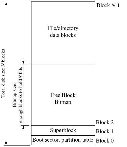
File systems typically reserve certain disk blocks at “easy-to-find” locations on the disk (such as the very start or the very end) to hold meta-data describing properties of the file system as a whole, such as the block size, disk size, any meta-data required to find the root directory, the time the file system was last mounted, the time the file system was last checked for errors, and so on. These special blocks are called superblocks.
Our file system will have exactly one superblock, which will always be at block 1 on the disk. Its layout is defined by struct Super in inc/fs.h. Block 0 is typically reserved to hold boot loaders and partition tables, so file systems generally do not use the very first disk block. Many “real” file systems maintain multiple superblocks, replicated throughout several widely-spaced regions of the disk, so that if one of them is corrupted or the disk develops a media error in that region, the other superblocks can still be found and used to access the file system.
File Meta-data
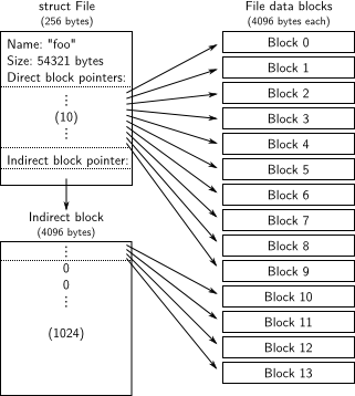
The layout of the meta-data describing a file in our file system is described by struct File in inc/fs.h. This meta-data includes the file’s name, size, type (regular file or directory), and pointers to the blocks comprising the file. As mentioned above, we do not have inodes, so this meta-data is stored in a directory entry on disk. Unlike in most “real” file systems, for simplicity we will use this one File structure to represent file meta-data as it appears both on disk and in memory.
The f_direct array in struct File contains space to store the block numbers of the first 10 (NDIRECT) blocks of the file, which we call the file’s direct blocks. For small files up to 104096 = 40KB in size, this means that the block numbers of all of the file’s blocks will fit directly within the File structure itself. For larger files, however, we need a place to hold the rest of the file’s block numbers. For any file greater than 40KB in size, therefore, we allocate an additional disk block, called the file’s *indirect block, to hold up to 4096/4 = 1024 additional block numbers. Our file system therefore allows files to be up to 1034 blocks, or just over four megabytes, in size. To support larger files, “real” file systems typically support double- and triple-indirect blocks as well.
Directories versus Regular Files
A File structure in our file system can represent either a regular file or a directory; these two types of “files” are distinguished by the type field in the File structure. The file system manages regular files and directory-files in exactly the same way, except that it does not interpret the contents of the data blocks associated with regular files at all, whereas the file system interprets the contents of a directory-file as a series of File structures describing the files and subdirectories within the directory.
The superblock in our file system contains a File structure (the root field in struct Super) that holds the meta-data for the file system’s root directory. The contents of this directory-file is a sequence of File structures describing the files and directories located within the root directory of the file system. Any subdirectories in the root directory may in turn contain more File structures representing sub-subdirectories, and so on.
FIle System Server
The Block Cache
In our file system, we will implement a simple “buffer cache” (really just a block cache) with the help of the processor’s virtual memory system. The code for the block cache is in fs/bc.c.
Our file system will be limited to handling disks of size 3GB or less. We reserve a large, fixed 3GB region of the file system environment’s address space, from 0x10000000 (DISKMAP) up to 0xD0000000 (DISKMAP+DISKMAX), as a “memory mapped” version of the disk. For example, disk block 0 is mapped at virtual address 0x10000000, disk block 1 is mapped at virtual address 0x10001000, and so on. The diskaddr function in fs/bc.c implements this translation from disk block numbers to virtual addresses (along with some sanity checking).
Since our file system environment has its own virtual address space independent of the virtual address spaces of all other environments in the system, and the only thing the file system environment needs to do is to implement file access, it is reasonable to reserve most of the file system environment’s address space in this way. It would be awkward for a real file system implementation on a 32-bit machine to do this since modern disks are larger than 3GB. Such a buffer cache management approach may still be reasonable on a machine with a 64-bit address space.
Of course, it would take a long time to read the entire disk into memory, so instead we’ll implement a form of demand paging, wherein we only allocate pages in the disk map region and read the corresponding block from the disk in response to a page fault in this region. This way, we can pretend that the entire disk is in memory.
The Block Bitmap
After fs_init sets the bitmap pointer, we can treat bitmap as a packed array of bits, one for each block on the disk. See, for example, block_is_free, which simply checks whether a given block is marked free in the bitmap.
// --------------------------------------------------------------
// Free block bitmap
// --------------------------------------------------------------

// Check to see if the block bitmap indicates that block 'blockno' is free.
// Return 1 if the block is free, 0 if not.
bool
block_is_free(uint32_t blockno)
{
	if (super == 0 || blockno >= super->s_nblocks)
		return 0;
	if (bitmap[blockno / 32] & (1 << (blockno % 32)))
		return 1;
	return 0;
}
File Operations
We have provided a variety of functions in fs/fs.c to implement the basic facilities you will need to interpret and manage File structures, scan and manage the entries of directory-files, and walk the file system from the root to resolve an absolute pathname. Read through all of the code in fs/fs.c and make sure you understand what each function does before proceeding.
// Find the disk block number slot for the 'filebno'th block in file 'f'.
// Set '*ppdiskbno' to point to that slot.
// The slot will be one of the f->f_direct[] entries,
// or an entry in the indirect block.
// When 'alloc' is set, this function will allocate an indirect block
// if necessary.
//
// Returns:
//	0 on success (but note that *ppdiskbno might equal 0).
//	-E_NOT_FOUND if the function needed to allocate an indirect block, but
//		alloc was 0.
//	-E_NO_DISK if there's no space on the disk for an indirect block.
//	-E_INVAL if filebno is out of range (it's >= NDIRECT + NINDIRECT).
//
// Analogy: This is like pgdir_walk for files.
// Hint: Don't forget to clear any block you allocate.
static int
file_block_walk(struct File *f, uint32_t filebno, uint32_t **ppdiskbno, bool alloc)
{
    // LAB 5: Your code here.
    if (filebno >= NDIRECT + NINDIRECT) {
        return -E_INVAL;
    }
    if (filebno < NDIRECT) {
        *ppdiskbno = &f->f_direct[filebno];
        return 0;
    }
    if (f->f_indirect == 0) {
        if (!alloc) {
               return -E_NOT_FOUND;
        }
        int r = alloc_block();
        if (r < 0) {
               return -E_NO_DISK;
        }
        f->f_indirect = r;
        memset(diskaddr(f->f_indirect), 0, BLKSIZE);
    }
    *ppdiskbno = (uint32_t *)diskaddr(f->f_indirect) + filebno - NDIRECT;
    return 0;
}

// Set *blk to the address in memory where the filebno'th
// block of file 'f' would be mapped.
//
// Returns 0 on success, < 0 on error.  Errors are:
//	-E_NO_DISK if a block needed to be allocated but the disk is full.
//	-E_INVAL if filebno is out of range.
//
// Hint: Use file_block_walk and alloc_block.
int
file_get_block(struct File *f, uint32_t filebno, char **blk)
{
    // LAB 5: Your code here.
    uint32_t *pdiskbno;
    int r = file_block_walk(f, filebno, &pdiskbno, 1);
    if (r < 0) {
        return r;
    }
    if (*pdiskbno == 0) {
        int r = alloc_block();
        if (r < 0) {
            return -E_NO_DISK;
        }
        *pdiskbno = r;
        memset(diskaddr(*pdiskbno), 0, BLKSIZE);
    }
    *blk = diskaddr(*pdiskbno);
    return 0;
}


// Read count bytes from f into buf, starting from seek position
// offset.  This meant to mimic the standard pread function.
// Returns the number of bytes read, < 0 on error.
ssize_t
file_read(struct File *f, void *buf, size_t count, off_t offset)
{
	int r, bn;
	off_t pos;
	char *blk;

	if (offset >= f->f_size)
		return 0;

	count = MIN(count, f->f_size - offset);

	for (pos = offset; pos < offset + count; ) {
		if ((r = file_get_block(f, pos / BLKSIZE, &blk)) < 0)
			return r;
		bn = MIN(BLKSIZE - pos % BLKSIZE, offset + count - pos);
		memmove(buf, blk + pos % BLKSIZE, bn);
		pos += bn;
		buf += bn;
	}

	return count;
}


// Write count bytes from buf into f, starting at seek position
// offset.  This is meant to mimic the standard pwrite function.
// Extends the file if necessary.
// Returns the number of bytes written, < 0 on error.
int
file_write(struct File *f, const void *buf, size_t count, off_t offset)
{
	int r, bn;
	off_t pos;
	char *blk;

	// Extend file if necessary
	if (offset + count > f->f_size)
		if ((r = file_set_size(f, offset + count)) < 0)
			return r;

	for (pos = offset; pos < offset + count; ) {
		if ((r = file_get_block(f, pos / BLKSIZE, &blk)) < 0)
			return r;
		bn = MIN(BLKSIZE - pos % BLKSIZE, offset + count - pos);
		memmove(blk + pos % BLKSIZE, buf, bn);
		pos += bn;
		buf += bn;
	}

	return count;
}
The file system interface
Now that we have the necessary functionality within the file system environment itself, we must make it accessible to other environments that wish to use the file system. Since other environments can’t directly call functions in the file system environment, we’ll expose access to the file system environment via a remote procedure call, or RPC, abstraction, built atop JOS’s IPC mechanism. Graphically, here’s what a call to the file system server (say, read) looks like
       Regular env           FS env
   +---------------+   +---------------+
   |      read     |   |   file_read   |
   |   (lib/fd.c)  |   |   (fs/fs.c)   |
...|.......|.......|...|.......^.......|...............
   |       v       |   |       |       | RPC mechanism
   |  devfile_read |   |  serve_read   |
   |  (lib/file.c) |   |  (fs/serv.c)  |
   |       |       |   |       ^       |
   |       v       |   |       |       |
   |     fsipc     |   |     serve     |
   |  (lib/file.c) |   |  (fs/serv.c)  |
   |       |       |   |       ^       |
   |       v       |   |       |       |
   |   ipc_send    |   |   ipc_recv    |
   |       |       |   |       ^       |
   +-------|-------+   +-------|-------+
           |                   |
           +-------------------+
Everything below the dotted line is simply the mechanics of getting a read request from the regular environment to the file system environment. Starting at the beginning, read (which we provide) works on any file descriptor and simply dispatches to the appropriate device read function, in this case devfile_read (we can have more device types, like pipes). devfile_read implements read specifically for on-disk files. This and the other devfile_* functions in lib/file.c implement the client side of the FS operations and all work in roughly the same way, bundling up arguments in a request structure, calling fsipc to send the IPC request, and unpacking and returning the results. The fsipc function simply handles the common details of sending a request to the server and receiving the reply.
The file system server code can be found in fs/serv.c. It loops in the serve function, endlessly receiving a request over IPC, dispatching that request to the appropriate handler function, and sending the result back via IPC. In the read example, serve will dispatch to serve_read, which will take care of the IPC details specific to read requests such as unpacking the request structure and finally call file_read to actually perform the file read.
Recall that JOS’s IPC mechanism lets an environment send a single 32-bit number and, optionally, share a page. To send a request from the client to the server, we use the 32-bit number for the request type (the file system server RPCs are numbered, just like how syscalls were numbered) and store the arguments to the request in a union Fsipc on the page shared via the IPC. On the client side, we always share the page at fsipcbuf; on the server side, we map the incoming request page at fsreq (0x0ffff000).
The server also sends the response back via IPC. We use the 32-bit number for the function’s return code. For most RPCs, this is all they return. FSREQ_READ and FSREQ_STAT also return data, which they simply write to the page that the client sent its request on. There’s no need to send this page in the response IPC, since the client shared it with the file system server in the first place. Also, in its response, FSREQ_OPEN shares with the client a new “Fd page”. We’ll return to the file descriptor page shortly.
Sharing library state across fork and spawn
The UNIX file descriptors are a general notion that also encompasses pipes, console I/O, etc. In JOS, each of these device types has a corresponding struct Dev, with pointers to the functions that implement read/write/etc. for that device type. lib/fd.c implements the general UNIX-like file descriptor interface on top of this. Each struct Fd indicates its device type, and most of the functions in lib/fd.c simply dispatch operations to functions in the appropriate struct Dev.
lib/fd.c also maintains the file descriptor table region in each application environment’s address space, starting at FDTABLE. This area reserves a page’s worth (4KB) of address space for each of the up to MAXFD (currently 32) file descriptors the application can have open at once. At any given time, a particular file descriptor table page is mapped if and only if the corresponding file descriptor is in use. Each file descriptor also has an optional “data page” in the region starting at FILEDATA, which devices can use if they choose.
We would like to share file descriptor state across fork and spawn, but file descriptor state is kept in user-space memory. Right now, on fork, the memory will be marked copy-on-write, so the state will be duplicated rather than shared. (This means environments won’t be able to seek in files they didn’t open themselves and that pipes won’t work across a fork.) On spawn, the memory will be left behind, not copied at all. (Effectively, the spawned environment starts with no open file descriptors.)
We will change fork to know that certain regions of memory are used by the “library operating system” and should always be shared. Rather than hard-code a list of regions somewhere, we will set an otherwise-unused bit in the page table entries (just like we did with the PTE_COW bit in fork).
We have defined a new PTE_SHARE bit in inc/lib.h. This bit is one of the three PTE bits that are marked “available for software use” in the Intel and AMD manuals. We will establish the convention that if a page table entry has this bit set, the PTE should be copied directly from parent to child in both fork and spawn. Note that this is different from marking it copy-on-write: as described in the first paragraph, we want to make sure to share updates to the page.
Network
Network Server
Writing a network stack from scratch is hard work. Instead, we will be using lwIP, an open source lightweight TCP/IP protocol suite that among many things includes a network stack. You can find more information on lwIP here. In this assignment, as far as we are concerned, lwIP is a black box that implements a BSD socket interface and has a packet input port and packet output port.
The network server is actually a combination of four environments:
- core network server environment (includes socket call dispatcher and lwIP)
- input environment
- output environment
- timer environment
The following diagram shows the different environments and their relationships. The diagram shows the entire system including the device driver, which will be covered later. In this lab, you will implement the parts highlighted in green.

The Core Network Server Environment
The core network server environment is composed of the socket call dispatcher and lwIP itself. The socket call dispatcher works exactly like the file server. User environments use stubs (found in lib/nsipc.c) to send IPC messages to the core network environment. If you look at lib/nsipc.c you will see that we find the core network server the same way we found the file server: i386_init created the NS environment with NS_TYPE_NS, so we scan envs, looking for this special environment type. For each user environment IPC, the dispatcher in the network server calls the appropriate BSD socket interface function provided by lwIP on behalf of the user.
Regular user environments do not use the nsipc_* calls directly. Instead, they use the functions in lib/sockets.c, which provides a file descriptor-based sockets API. Thus, user environments refer to sockets via file descriptors, just like how they referred to on-disk files. A number of operations (connect, accept, etc.) are specific to sockets, but read, write, and close go through the normal file descriptor device-dispatch code in lib/fd.c. Much like how the file server maintained internal unique ID’s for all open files, lwIP also generates unique ID’s for all open sockets. In both the file server and the network server, we use information stored in struct Fd to map per-environment file descriptors to these unique ID spaces.
Even though it may seem that the IPC dispatchers of the file server and network server act the same, there is a key difference. BSD socket calls like accept and recv can block indefinitely. If the dispatcher were to let lwIP execute one of these blocking calls, the dispatcher would also block and there could only be one outstanding network call at a time for the whole system. Since this is unacceptable, the network server uses user-level threading to avoid blocking the entire server environment. For every incoming IPC message, the dispatcher creates a thread and processes the request in the newly created thread. If the thread blocks, then only that thread is put to sleep while other threads continue to run.
In addition to the core network environment there are three helper environments. Besides accepting messages from user applications, the core network environment’s dispatcher also accepts messages from the input and timer environments.
void
umain(int argc, char **argv)
{
	envid_t ns_envid = sys_getenvid();

	binaryname = "ns";

	// fork off the timer thread which will send us periodic messages
	timer_envid = fork();
	if (timer_envid < 0)
		panic("error forking");
	else if (timer_envid == 0) {
		timer(ns_envid, TIMER_INTERVAL);
		return;
	}

	// fork off the input thread which will poll the NIC driver for input
	// packets
	input_envid = fork();
	if (input_envid < 0)
		panic("error forking");
	else if (input_envid == 0) {
		input(ns_envid);
		return;
	}

	// fork off the output thread that will send the packets to the NIC
	// driver
	output_envid = fork();
	if (output_envid < 0)
		panic("error forking");
	else if (output_envid == 0) {
		output(ns_envid);
		return;
	}

	// lwIP requires a user threading library; start the library and jump
	// into a thread to continue initialization.
	thread_init();
	thread_create(0, "main", tmain, 0);
	thread_yield();
	// never coming here!
}
The Output Environment
When servicing user environment socket calls, lwIP will generate packets for the network card to transmit. LwIP will send each packet to be transmitted to the output helper environment using the NSREQ_OUTPUT IPC message with the packet attached in the page argument of the IPC message. The output environment is responsible for accepting these messages and forwarding the packet on to the device driver via the system call interface that you will soon create.
void
output(envid_t ns_envid)
{
	binaryname = "ns_output";

	// LAB 6: Your code here:
	// 	- read a packet from the network server
	//	- send the packet to the device driver
    uint32_t  req, whom;
    int r;

    while(true) {
        req = ipc_recv((int32_t *) &whom, &nsipcbuf, 0);
        if (whom != ns_envid) {
            cprintf("NS OUTPUT: got IPC message from env %x not NS\n", whom);
            continue;
        }
        if (req != NSREQ_OUTPUT) {
            cprintf("NS OUTPUT: got IPC message type %d not NSREQ_OUTPUT\n", req);
            continue;
        }

        while((r = sys_transmit_packet(nsipcbuf.pkt.jp_data, nsipcbuf.pkt.jp_len)) == -E_TX_FULL) {
            sys_yield();
        }

        if (r < 0) {
            panic("NS OUTPUT: sys_transmit_packet: %e", r);
        }
    }
}
The Input Environment
Packets received by the network card need to be injected into lwIP. For every packet received by the device driver, the input environment pulls the packet out of kernel space (using kernel system calls that you will implement) and sends the packet to the core server environment using the NSREQ_INPUT IPC message.
The packet input functionality is separated from the core network environment because JOS makes it hard to simultaneously accept IPC messages and poll or wait for a packet from the device driver. We do not have a select system call in JOS that would allow environments to monitor multiple input sources to identify which input is ready to be processed.
void
input(envid_t ns_envid)
{
	binaryname = "ns_input";

	// LAB 6: Your code here:
	// 	- read a packet from the device driver
	//	- send it to the network server
	// Hint: When you IPC a page to the network server, it will be
	// reading from it for a while, so don't immediately receive
	// another packet in to the same physical page.
    uint8_t buf[2048];
    int r, i;
    while(true) {
        while((r = sys_receive_packet(buf, sizeof(buf))) == -E_RX_EMPTY) {
            sys_yield();
        }
        if (r < 0) {
            panic("NS INPUT: sys_receive_packet: %e", r);
        }

        nsipcbuf.pkt.jp_len = r;
        memmove(nsipcbuf.pkt.jp_data, buf, r);

        ipc_send(ns_envid, NSREQ_INPUT, &nsipcbuf, PTE_P|PTE_W|PTE_U);

        // wait for the network server to process the packet
        sys_yield();
        sys_yield();
        sys_yield();
        sys_yield();
        sys_yield();
        sys_yield();
    }
}
The Timer Environment
The timer environment periodically sends messages of type NSREQ_TIMER to the core network server notifying it that a timer has expired. The timer messages from this thread are used by lwIP to implement various network timeouts.
Network Interface Card Driver
PCI Interface
The E1000 is a PCI device, which means it plugs into the PCI bus on the motherboard. The PCI bus has address, data, and interrupt lines, and allows the CPU to communicate with PCI devices and PCI devices to read and write memory. A PCI device needs to be discovered and initialized before it can be used. Discovery is the process of walking the PCI bus looking for attached devices. Initialization is the process of allocating I/O and memory space as well as negotiating the IRQ line for the device to use.
We have provided you with PCI code in kern/pci.c. To perform PCI initialization during boot, the PCI code walks the PCI bus looking for devices. When it finds a device, it reads its vendor ID and device ID and uses these two values as a key to search the pci_attach_vendor array. The array is composed of struct pci_driver entries like this:
struct pci_driver {
    uint32_t key1, key2;
    int (*attachfn) (struct pci_func *pcif);
};
If the discovered device’s vendor ID and device ID match an entry in the array, the PCI code calls that entry’s attachfn to perform device initialization. (Devices can also be identified by class, which is what the other driver table in kern/pci.c is for.)
The attach function is passed a PCI function to initialize. A PCI card can expose multiple functions, though the E1000 exposes only one. Here is how we represent a PCI function in JOS:
struct pci_func {
    struct pci_bus *bus;

    uint32_t dev;
    uint32_t func;

    uint32_t dev_id;
    uint32_t dev_class;

    uint32_t reg_base[6];
    uint32_t reg_size[6];
    uint8_t irq_line;
};
The above structure reflects some of the entries found in Table 4-1 of Section 4.1 of the developer manual. The last three entries of struct pci_func are of particular interest to us, as they record the negotiated memory, I/O, and interrupt resources for the device. The reg_base and reg_size arrays contain information for up to six Base Address Registers or BARs. reg_base stores the base memory addresses for memory-mapped I/O regions (or base I/O ports for I/O port resources), reg_size contains the size in bytes or number of I/O ports for the corresponding base values from reg_base, and irq_line contains the IRQ line assigned to the device for interrupts. The specific meanings of the E1000 BARs are given in the second half of table 4-2.
When the attach function of a device is called, the device has been found but not yet enabled. This means that the PCI code has not yet determined the resources allocated to the device, such as address space and an IRQ line, and, thus, the last three elements of the struct pci_func structure are not yet filled in. The attach function should call pci_func_enable, which will enable the device, negotiate these resources, and fill in the struct pci_func.
Memory-mapped I/O
Software communicates with the E1000 via memory-mapped I/O (MMIO). You’ve seen this twice before in JOS: both the CGA console and the LAPIC are devices that you control and query by writing to and reading from “memory”. But these reads and writes don’t go to DRAM; they go directly to these devices.
pci_func_enable negotiates an MMIO region with the E1000 and stores its base and size in BAR 0 (that is, reg_base[0] and reg_size[0]). This is a range of physical memory addresses assigned to the device, which means you’ll have to do something to access it via virtual addresses. Since MMIO regions are assigned very high physical addresses (typically above 3GB), you can’t use KADDR to access it because of JOS’s 256MB limit. Thus, you’ll have to create a new memory mapping. We’ll use the area above MMIOBASE (your mmio_map_region from lab 4 will make sure we don’t overwrite the mapping used by the LAPIC). Since PCI device initialization happens before JOS creates user environments, you can create the mapping in kern_pgdir and it will always be available.
DMA
You could imagine transmitting and receiving packets by writing and reading from the E1000’s registers, but this would be slow and would require the E1000 to buffer packet data internally. Instead, the E1000 uses Direct Memory Access or DMA to read and write packet data directly from memory without involving the CPU. The driver is responsible for allocating memory for the transmit and receive queues, setting up DMA descriptors, and configuring the E1000 with the location of these queues, but everything after that is asynchronous. To transmit a packet, the driver copies it into the next DMA descriptor in the transmit queue and informs the E1000 that another packet is available; the E1000 will copy the data out of the descriptor when there is time to send the packet. Likewise, when the E1000 receives a packet, it copies it into the next DMA descriptor in the receive queue, which the driver can read from at its next opportunity.
The receive and transmit queues are very similar at a high level. Both consist of a sequence of descriptors. While the exact structure of these descriptors varies, each descriptor contains some flags and the physical address of a buffer containing packet data (either packet data for the card to send, or a buffer allocated by the OS for the card to write a received packet to).
The queues are implemented as circular arrays, meaning that when the card or the driver reach the end of the array, it wraps back around to the beginning. Both have a head pointer and a tail pointer and the contents of the queue are the descriptors between these two pointers. The hardware always consumes descriptors from the head and moves the head pointer, while the driver always add descriptors to the tail and moves the tail pointer. The descriptors in the transmit queue represent packets waiting to be sent (hence, in the steady state, the transmit queue is empty). For the receive queue, the descriptors in the queue are free descriptors that the card can receive packets into (hence, in the steady state, the receive queue consists of all available receive descriptors). Correctly updating the tail register without confusing the E1000 is tricky; be careful!
The pointers to these arrays as well as the addresses of the packet buffers in the descriptors must all be physical addresses because hardware performs DMA directly to and from physical RAM without going through the MMU.
Transmitting Packets
As an example, consider the legacy transmit descriptor given in table 3-8 of the manual and reproduced here:
63            48 47   40 39   32 31   24 23   16 15             0
  +---------------------------------------------------------------+
  |                         Buffer address                        |
  +---------------+-------+-------+-------+-------+---------------+
  |    Special    |  CSS  | Status|  Cmd  |  CSO  |    Length     |
  +---------------+-------+-------+-------+-------+---------------+
The first byte of the structure starts at the top right, so to convert this into a C struct, read from right to left, top to bottom. If you squint at it right, you’ll see that all of the fields even fit nicely into a standard-size types:
struct tx_desc
{
	uint64_t addr;
	uint16_t length;
	uint8_t cso;
	uint8_t cmd;
	uint8_t status;
	uint8_t css;
	uint16_t special;
};
Your driver will have to reserve memory for the transmit descriptor array and the packet buffers pointed to by the transmit descriptors. There are several ways to do this, ranging from dynamically allocating pages to simply declaring them in global variables. Whatever you choose, keep in mind that the E1000 accesses physical memory directly, which means any buffer it accesses must be contiguous in physical memory.
There are also multiple ways to handle the packet buffers. The simplest, which we recommend starting with, is to reserve space for a packet buffer for each descriptor during driver initialization and simply copy packet data into and out of these pre-allocated buffers. The maximum size of an Ethernet packet is 1518 bytes, which bounds how big these buffers need to be. More sophisticated drivers could dynamically allocate packet buffers (e.g., to reduce memory overhead when network usage is low) or even pass buffers directly provided by user space (a technique known as “zero copy”), but it’s good to start simple.
Now that transmit is initialized, you’ll have to write the code to transmit a packet and make it accessible to user space via a system call. To transmit a packet, you have to add it to the tail of the transmit queue, which means copying the packet data into the next packet buffer and then updating the TDT (transmit descriptor tail) register to inform the card that there’s another packet in the transmit queue. (Note that TDT is an index into the transmit descriptor array, not a byte offset; the documentation isn’t very clear about this.)

int
e1000_transmit(const void *buf, size_t size)
{
    int tail = E1000_REG(E1000_TDT);

    if (size > ETH_PKT_SIZE) {
        return -E_PKT_TOO_LARGE;
    }

    if ((e1000_tx_queue[tail].cmd & E1000_TXD_CMD_RS) && !(e1000_tx_queue[tail].status & E1000_TXD_STAT_DD)) {
        return -E_TX_FULL;
    }

    e1000_tx_queue[tail].status &= ~E1000_TXD_STAT_DD;
    memcpy(e1000_tx_buf[tail], buf, size);
    e1000_tx_queue[tail].length = size;
    e1000_tx_queue[tail].cmd |= E1000_TXD_CMD_RS | E1000_TXD_CMD_EOP;

    E1000_REG(E1000_TDT) = (tail + 1) % NTXDESC;

    return 0;
}
Receiving Packets
Just like you did for transmitting packets, you’ll have to configure the E1000 to receive packets and provide a receive descriptor queue and receive descriptors.
The receive queue is very similar to the transmit queue, except that it consists of empty packet buffers waiting to be filled with incoming packets. Hence, when the network is idle, the transmit queue is empty (because all packets have been sent), but the receive queue is full (of empty packet buffers).
When the E1000 receives a packet, it first checks if it matches the card’s configured filters (for example, to see if the packet is addressed to this E1000’s MAC address) and ignores the packet if it doesn’t match any filters. Otherwise, the E1000 tries to retrieve the next receive descriptor from the head of the receive queue. If the head (RDH) has caught up with the tail (RDT), then the receive queue is out of free descriptors, so the card drops the packet. If there is a free receive descriptor, it copies the packet data into the buffer pointed to by the descriptor, sets the descriptor’s DD (Descriptor Done) and EOP (End of Packet) status bits, and increments the RDH.
If the E1000 receives a packet that is larger than the packet buffer in one receive descriptor, it will retrieve as many descriptors as necessary from the receive queue to store the entire contents of the packet. To indicate that this has happened, it will set the DD status bit on all of these descriptors, but only set the EOP status bit on the last of these descriptors. You can either deal with this possibility in your driver, or simply configure the card to not accept “long packets” (also known as jumbo frames) and make sure your receive buffers are large enough to store the largest possible standard Ethernet packet (1518 bytes).
Software adds receive descriptors by writing the tail pointer with the index of the entry beyond the last valid descriptor. As packets arrive, they are stored in memory and the head pointer is incremented by hardware. When the head pointer is equal to the tail pointer, the ring is empty. Hardware stops storing packets in system memory until software advances the tail pointer, making more receive buffers available.

int
e1000_receive(void *buf, size_t size)
{
    int tail = E1000_REG(E1000_RDT);
    int next = (tail + 1) % NRXDESC;
    int length;

    if (!(e1000_rx_queue[next].status & E1000_RXD_STAT_DD)) {
        return -E_RX_EMPTY;
    }

    if ((length = e1000_rx_queue[next].length) > size) {
        return -E_PKT_TOO_LARGE;
    }

    memcpy(buf, e1000_rx_buf[next], length);
    e1000_rx_queue[next].status &= ~E1000_RXD_STAT_DD;

    E1000_REG(E1000_RDT) = next;

    return length;
}
Reference
https://pdos.csail.mit.edu/6.828/2018/schedule.html
https://qiita.com/kagurazakakotori/items/b092fc0dbe3c3ec09e8e